Announcement

Collapse
No announcement yet.

Electrical & Fusebox Upgrade on the GS550/650B

Collapse
X
 
  • Filter
  • Time
  • Show
Clear All
new posts

    Electrical & Fusebox Upgrade on the GS550/650B

    I have just completed the electrical repair and upgrade on the wiring of my GS550/650B motorcycle. It includes an upgrade from a single fuse system that powers the complete electrical setup on the bike to a system with six fuses as well as a general upgrade of wiring within the 33 year old harness.

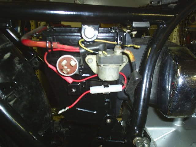
    First a picture of the old single fuse setup where everything on the bike ran through this fuse to receive power from the battery, also the charging went through this fuse to the battery as well from the R/R and stator.
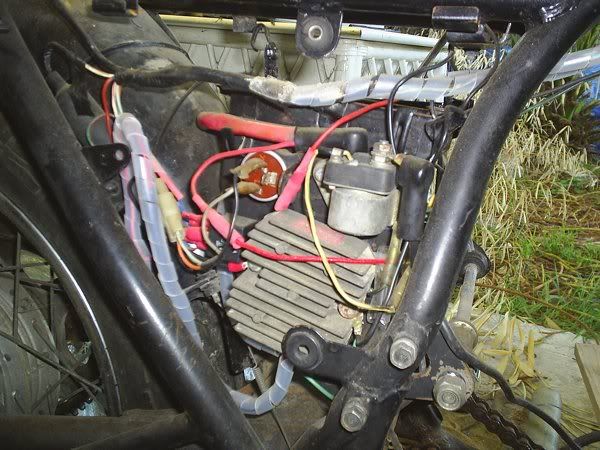


    After removing the complete harness from the frame I unwrapped the electrical tape and other protective coverings from it that had gathered over the last 30 odd years and was left with a bunch of loose wires on the work bench.
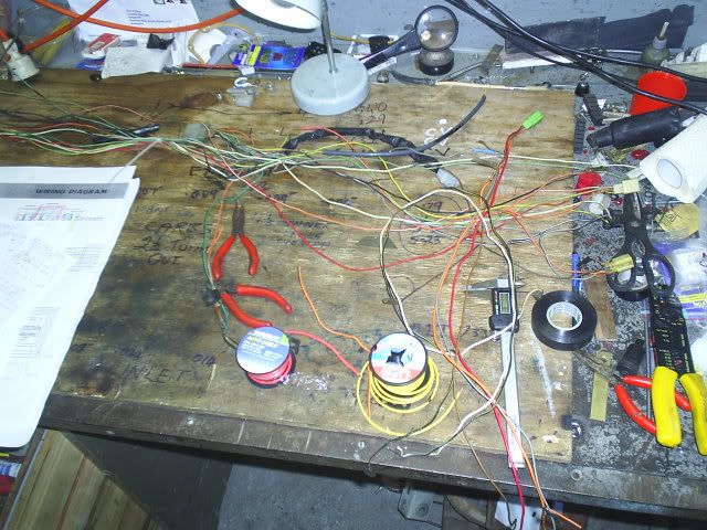


    I zip tied the loom in 5 or 6 places to keep the wires in place and then cleaned each individual wire down with unleaded petrol. After they were all clean I then sprayed brake cleaner on a rag and wiped each of the wires clean with that. A quick blow off with compressed air and it all looked like new. A very messy job though. I used gloves to protect my hands from the petrol and brake cleaner.
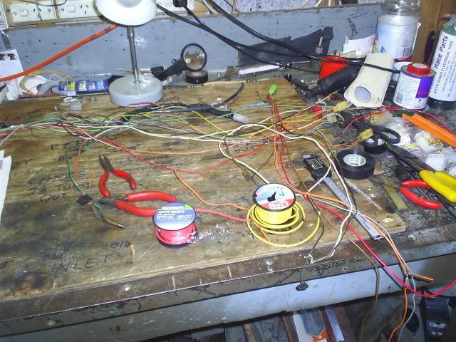


    I then did a trial fit of the loom on the frame and made note of which wires needed to be lengthened, etc.
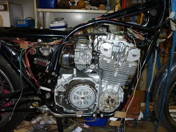


    I cut out the bodged up stuff that had been done to the loom over the years. I also ran the new wires required for the 6 fuse upgrade. That included the three 15 amp wires, one an EARTH from end to end that pigtails would run off, the major RED wire from the fuse box to the ignition switch and the green wires from the ignition switch back to the fuse box to feed the other four fuses that would go to the circuits for the 1) coils, kill sw. & starter button, 2) blinkers, 3) lights & 4) front & rear brake lights, horn, oil pressure & neutral light.

    I spliced in the wires from the RH GS650 switch that I had decided to use. That meant that the ON/OFF switch for the lights was now on the RH side of the bars instead of being on the LH side with the dimmer switch. I also wired up the passing button on the LH switch. BTW the LH switch is from a XJ650 Yamaha (sorry, but has a much better choke arrangement than the plastic thing on the GS bikes).
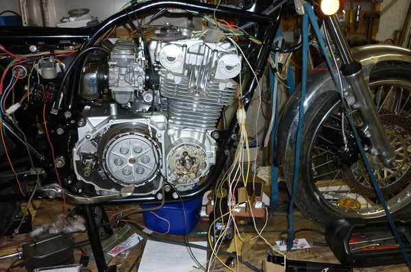


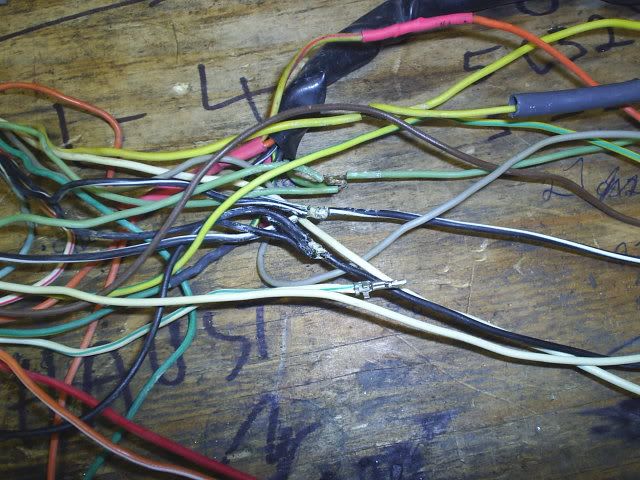
    I lengthened the wires, stripped and soldered them and shrunk the heatshrink over the joins. I also cut away and replaced old bullet connectors with new ones as necessary.


    I then taped up the wiring loom with new electrical tape ready for the final fitment to the frame.
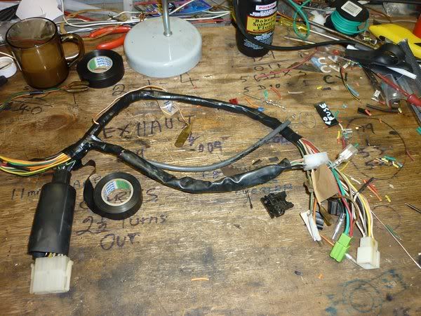


    I still had to mount the new fuse box and the Honda R/R to the frame. After the wiring was covered with the new tape with 1/3 overlap the loom was fitted back onto the bike/frame. A couple of the pig tails I had done off the new 15 amp earth wire were a bit short so I had to lengthen them appropriately.
    Last edited by Guest; 11-21-2010, 08:46 PM.

    #2
    Next Installment

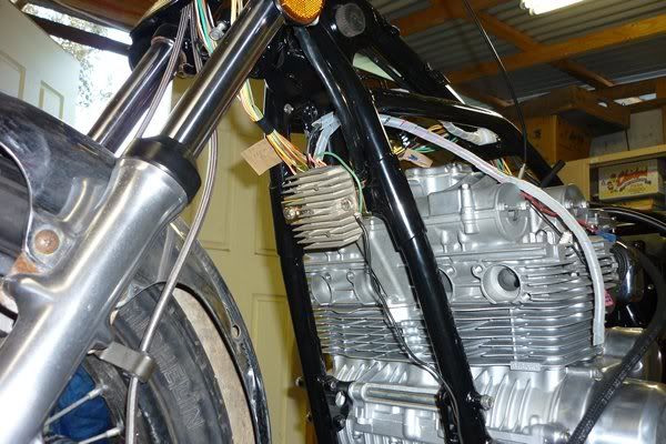
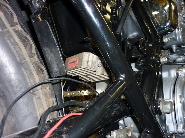
    I was lacking space on the side of the air box because the new fusebox needed to go there so I initially decided to mount the R/R on the front down tubes of the frame as shown below.


    Then on the advice of Jim (POS) and Andre (Matchless) I was told the red, black
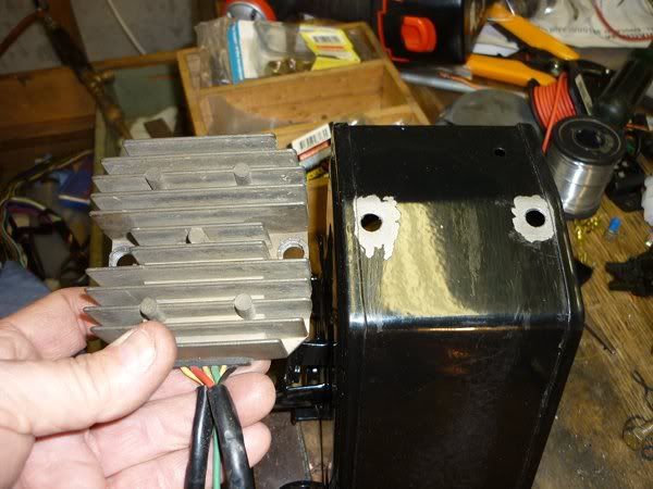
    and green wires would have a long run from the R/R unit back to the battery and that was not good. So on Andre’s advice I pulled the air box off the bike and drilled the bottom of it to accept the R/R unit. This worked very well, although I would have preferred to have the fins running length wise so air could pass through them as the bike is moving.


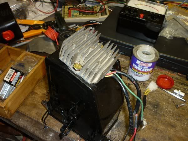
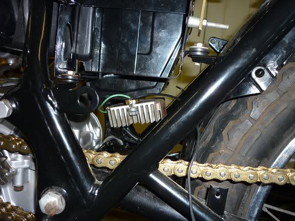
    When installed the R/R looks like this. I installed two large brass nuts between the R/R base and the airbox to allow air to pass through for better cooling. The brass nuts with dialectic grease provide a good earth to the airbox which is earthed through the solenoid mounting bracket. The pig tail on the end of the R/R earth is then run to the battery “-ive” as in the picture.


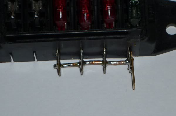
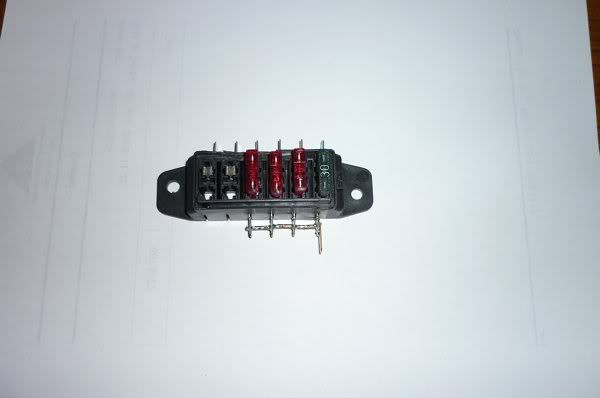
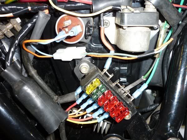
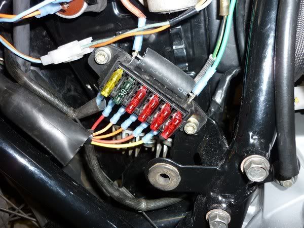
    I then had to link four of the fuses together in the fusebox so when the ignition was turned ON the four circuits would all receive power. This was done by drilling out the holes in the male spade terminals on the fusebox and passing a length of 15 amp wire through them and soldering it in place and extending one of the spade terminals to take the female spade connector from the wiring harness as this would not push on normally because the 15 amp wire was preventing this from happening.


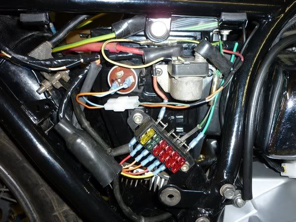
    I then fitted the 6-way fusebox and ran the wiring to the fusebox. I fitted a 4-way connector for the four circuit wires so they could be unplugged easily if need be. This connector is housed in the rubber boot adjacent to the fusebox.

    I then also ran the red wire from the R/R to the fusebox charging the system through a 30 amp fuse. I then tested the complete circuit and as everything worked ok I was very happy with the result and can now move on to other things to finish this total refurbishment of the bike.


    Also I tested the connection from the engine fins to one of the earth pig tail lugs and obtained a reading of 75 ohms (not good), so I ran another earth from the motor to the harness earth wire and this figure dropped to 1 ohm – now I am happy. Up until I added this extra wire I had trouble with some of my testing results (i.e. some things did not work as they should have).

    I reckon I have about one or two hours work until startup. After 2 ˝ to 3 years it will be good to hear those pipes rumble again.

    As I have had no one to physically help me with this project – have done it all on my own, I would like to thank all those who have given advice and help in any other ways. Worthy of special note are Andre, Jim and Ed.

    Thanks guys. I have learnt a lot, not least of all degreeing cams for the first time.

    Thanks again

    Don

    Comment


      #3
      Don,
      That is looking much better. Painstaking work. I'm really glad my ED has a new harness avaliable.

      I'm sure you have something in mind to protect those hot connections on the fusebox. Maybe just some of that paint on electrical insulation. Comes in black or other colors.

      Nice work.
      Jim

      Comment


        #4
        Jim, just for you, although Andre sent me an email and commented on the same thing. You two guys must think alike, that's a worry. I have used a piece of 5/16" rubber fuel hose slit along it's length and fitted as a temporary measure to protect the "hot" side of the fusebox. I will have to look around for a more permanent solution, perhaps a rubberised paint on product like you suggested. May be hard to find over here though, maybe I could use epoxy.


        Last edited by Guest; 07-20-2010, 05:54 PM.

        Comment


          #5
          Very nice job Don!

          Oh, and epoxy will work just fine to insulate the ends there. You could even go so far as to make a masking tape form around the side of the fuse block, then mix and pour the epoxy in to get a clean uniform shape for it.
          I have even been known to add in a drop or two of dye to tint the epoxy black to match the rest of the plastic around it.

          Cheers, and once again, great job!

          Comment


            #6
            Thanks Mac. Good idea there. I will definitely make up a masking tape dam to pour the epoxy into.

            I haven't really been putting all of my project up on this site as the progress has been going along. It has been about 2 1/2 years now since I took the 550 off the road. It is getting very close to the startup stage now. I filled the motor with oil last night, removed the spark plugs and cranked the motor for a good while until the oil pressure light went out. BTW does that mean that the oil has got up to the cams, etc.

            I was going to do the coil relay mod, but when I checked the voltage at the coils it was 12.45v so I didn't bother
            Last edited by Guest; 07-21-2010, 04:26 PM.

            Comment


              #7
              Don,
              You must be the most patient person I know! I would have hotwired it just to hear it run.
              You will never regret redoing the complete wiring on your bike, now you know it intimately and you also know its good.

              Your bike is really looking good and I am sure she is going to give you a lot of pleasure!
              Keep well.

              Comment


                #8
                Originally posted by Matchless View Post
                Don,
                You must be the most patient person I know! I would have hotwired it just to hear it run.
                You will never regret redoing the complete wiring on your bike, now you know it intimately and you also know its good.

                Your bike is really looking good and I am sure she is going to give you a lot of pleasure!
                Keep well.
                Andre, you're up early, it's 6.40am here. Have you got a big day ahead of you. Thanks for the encouragement.

                One other problem I discovered when getting the bike off the work platform was that the right front caliper is dragging very heavily on the disc. All parts are brand new with new fluid and S/S braklelines. Don't know what can be wrong there. Maybe the pistons are worn in relation to the bores although I am sure I miked them when they were on the bench. Ah well, more patience required.
                Thanks again
                Last edited by Guest; 11-21-2010, 09:38 PM.

                Comment

                Working...
                X