A
AX2007
Guest
I'm having trouble with the clutch adjustment on my T. I have a brand new OEM cable, and this is how I tried to adjust it after installation:
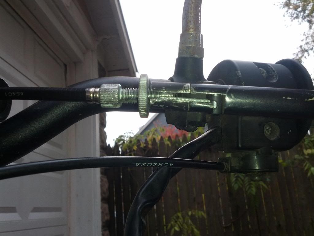
1. Fully screw in the cable at the lever.
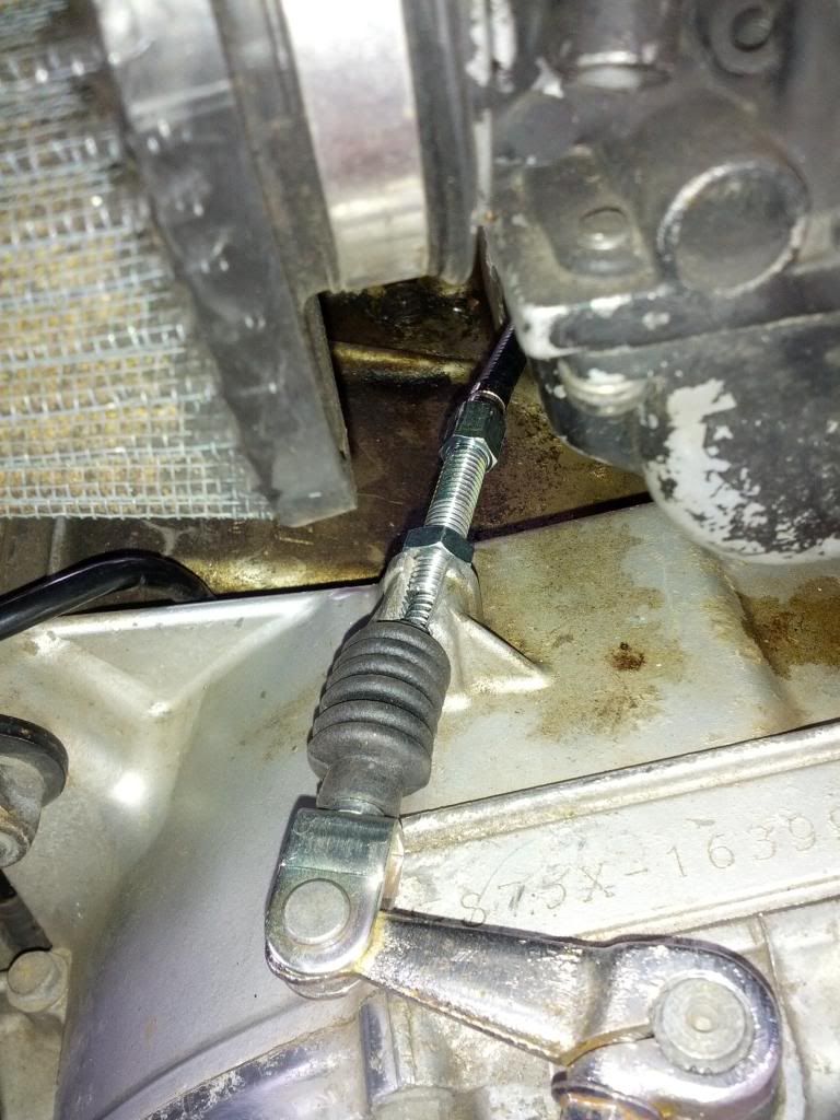
2. Fully screw in the hollow screw that is on top of the transmission case.
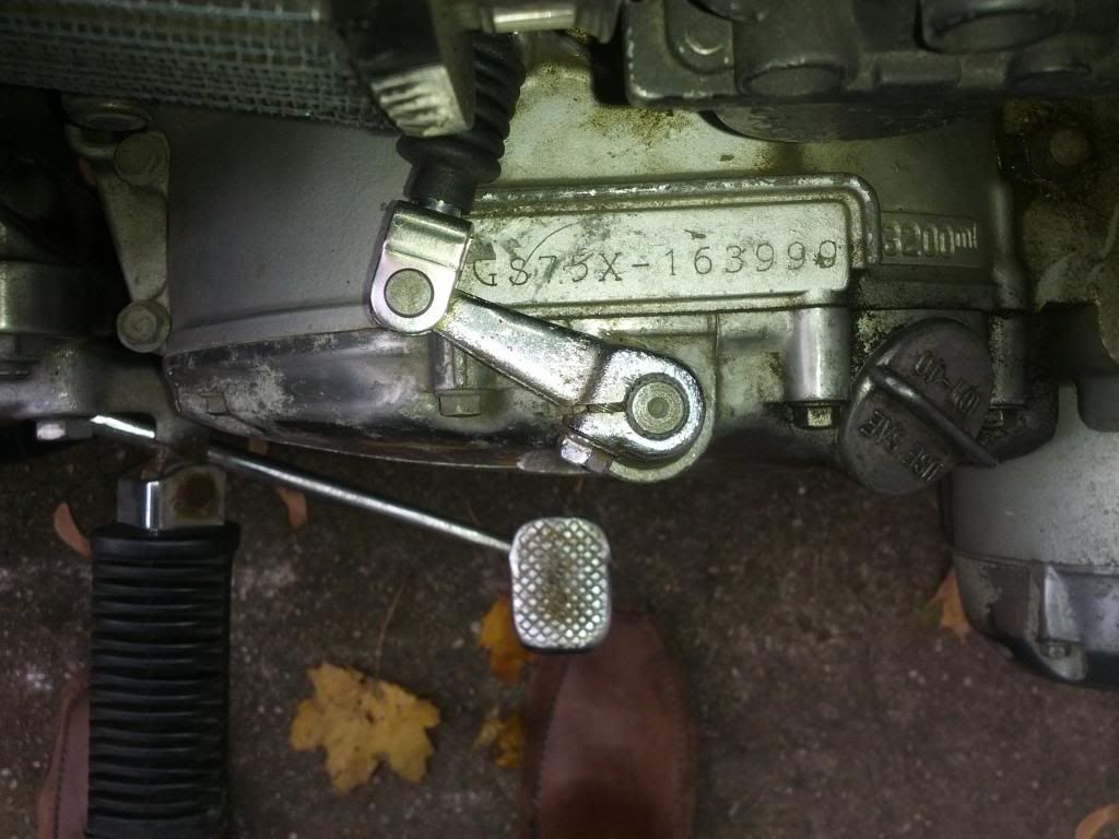
3. Set clutch arm (at the transmission) parallel with the transmission case.
4. Unscrew hollow screw until there is about 4-5 millimeters of play at the clutch lever.
5. fine tune at the lever.
Is this correct? The problem I'm having is I'm not sure how far out the hollow screw should be... On my bike it is only holding on with about 4 or 5 threads. I also have the screw at the lever about halfway out. It doesn't look correct, but that may just be how it is. Any thoughts?
On a related note, the clutch slipping I was experiencing with the old cable is gone (from a short 5 mile ride this morning). And the clutch is much lighter and easier than it was previously, with greater "feel".
1. Fully screw in the cable at the lever.
2. Fully screw in the hollow screw that is on top of the transmission case.
3. Set clutch arm (at the transmission) parallel with the transmission case.
4. Unscrew hollow screw until there is about 4-5 millimeters of play at the clutch lever.
5. fine tune at the lever.
Is this correct? The problem I'm having is I'm not sure how far out the hollow screw should be... On my bike it is only holding on with about 4 or 5 threads. I also have the screw at the lever about halfway out. It doesn't look correct, but that may just be how it is. Any thoughts?
On a related note, the clutch slipping I was experiencing with the old cable is gone (from a short 5 mile ride this morning). And the clutch is much lighter and easier than it was previously, with greater "feel".