• Required reading for all forum users!!!

    Welcome!
    Register to access the full functionality of the GSResources forum. Until you register and activate your account you will not have full forum access, nor will you be able to post or reply to messages.

    A note to new registrants...
    All new forum registrations must be activated via email before you have full access to the forum.

    A Special Note about Email accounts!
    DO NOT SIGN UP USING hotmail, outlook, gmx, sbcglobal, att, bellsouth or email.com. They delete our forum signup emails.

    A note to old forum members...
    I receive numerous requests from people who can no longer log in because their accounts were deleted. As mentioned in the forum FAQ, user accounts are deleted if you haven't logged in for the past 6 months. If you can't log in, then create a new forum account. If you don't get an error message, then check your email account for an activation message. If you get a message stating that the email address is already in use, then your account still exists so follow the instructions in the forum FAQ for resetting your password.

    Have you forgotten your password or have a new email address? Then read the forum FAQ for details on how to reset it.

    Any email requests for "can't log in anymore" problems or "lost my password" problems will be deleted. Read the forum FAQ and follow the instructions there - that's what we have one for...

  • Returning Visitors

    If you are a returning visitor who never received your confirmation email, then odds are your email provider is blockinig emails from our server. The only thing that can be done to get around this is you will have to try creating another forum account using an email address from another domain.

    If you are a returning visitor to the forum and can't log in using your old forum name and password but used to be able to then chances are your account is deleted. Purges of the databases are done regularly. You will have to create a new forum account and you should be all set.

I am impressed!

Steve

GS Whisperer
After outlining some charging problems in this thread, I ordered a wiring harness from Eastern Beaver (scroll to bottom of page) on Sunday afternoon.
Got an e-mail Monday morning saying it had been shipped. It arrived today, on Friday. IT CAME FROM JAPAN in just four days. :clap: :clap:

The product is impressive. I ordered it with the Yazaki connector for the stator. No particular reason, just thought I would go with the black connector.
shrug1.gif


I am getting ready to change the tires and brake pads on my Wing right now, will attack the wiring harness on her 850 when I get done with that.
Will report results when I am done. :D

.
 
Hi Mr. Steve,

I'm impressed that you've been impressed. That's impressive. Those wiring products look great. Have fun wrenching. :)


Thank you for your indulgence,

BassCliff
 
Six hours and a few minutes later, the tires and brakes are changed on the Wing. :eek:

Now to attack the wiring on her bike.
run1.gif


.
 
That harness looks killer Steve! I'm seriously jealous. In comparison I took my FET R/R today and used silicone to seal the plug cavity - barbaric compared to that harness. I did find some nice Teflon coated wire to use at least - it's significantly thinner than the PVC coated stuff Suzuki used, plus used a MIL Spec silicone tht is purpose built to seal electrical components. At any rate, please post some photos after you get everything installed.:)
 
I am going to have to dig the black silicone out of there from when I installed it last week, but I will get pictures of what I can.

Thanks for the reminder/invitation to do so.

Of course, with the other modifications I have made on that side, you might not be able to see much, so I had better get some pics before it's installed.


.
 
OK, install tutorial ... WITH PICTURES.

Started on the left side of the bike.
IMG_2348.jpg


Pulled the side cover to reveal a couple of previous mods.
The front (left) relay turns the headlight OFF when the starter button is pressed.
The rear (right) relay provides power to the terminal strip on the other side of the bike.
IMG_2349.jpg


Pulled the right cover
IMG_2353.jpg


to reveal the terminal strip.
IMG_2356.jpg


The top two rows are bridged together and are fed by the relay on the other side. They have power only when the key is ON. The other wires connected to these top two rows provide power to the CB radio, GPS and XM satellite radio. I used to have the sense wire for the Honda r/r connected here, too, but that is no longer needed.

The third, fourth and fifth rows are for other items that needed a good connection, including the LED driving lights and the LED strips on the gas tank. The two switches in the lower right corner are fed by those terminals.

The two lowest rows are also bridged toghether, they are both grounded, which should be obvious by the black wire that loops to the mounting bolt.
 
The rectifier/regulator (r/r) on this bike is mounted under the battery box. There is not a lot of room between it and the swingarm to get the bolts in and out, so I have found it easier to remove the battery box to change the r/r. It is necessary to remove the two screws between the starter solenoid and the fuse box on the left side to remove the left side panel (it stays with the bike), then remove the turn signal flasher and the self-cancelling control unit from their hangers on the right side to remove the battery box.

After removing the battery, here is what you see:
IMG_2377.jpg


After removing the battery box itself, this is what you see:
IMG_2376.jpg


.
 
I had previously mounted the FET r/r last week and filled the terminal cavities with black silicone for waterproofing.
Here is what it looked like when removed:
IMG_2357.jpg


A close-up of the wires and silicone:
IMG_2358.jpg


Spent some time digging out the silicone after pulling the wires out.
IMG_2365.jpg


I am somewhat pleased with the way it finally turned out.
IMG_2366.jpg


.
 
I had ordered this harness from Eastern Beaver:
frk250-a_1109.jpg


It comes with a matching harness for the stator:
a_frk-250-b_1110.jpg


I checked to see if the connectors would fit in the cleaned-out areas, found there was no problem.
IMG_2367.jpg


.
 
Now to get the bike ready for the harness.

Here are the bullet connectors that were installed a year ago when I got a Honda r/r from Duaneage.
IMG_2369.jpg


I cut them off and installed one of the spade connectors that came with the harness.
IMG_2370.jpg


Three new spade connectors, crimped, then soldered.
IMG_2374.jpg


The spade connectors installed into their new housing that mates with the "Part B" harness to the r/r:
IMG_2375.jpg


.
 
There is a fuse holder in the harness that hold a mini 30-amp fuse. It has a convenient mounting tab in its cover.
IMG_2379.jpg


I chose to mount it behind the relay mounting tab on the left side, so I needed to make accomodations for an off-center mounting screw:
IMG_2380.jpg


Here is the housing, mounted behind the relay tab:
IMG_2381.jpg


Here is the harness, installed into the fuse holder cap:
IMG_2382.jpg


.
 
I determined how long to leave the wires in the new harness by routing them to the battery terminals. I usually like to minimize the number of connections directly to the battery, but thought I would make an exception in this case. Here are the battery terminals, crimped and soldered:
IMG_2389.jpg


Threre are a couple pieces of shrink-wrap tubing included with the kit, they are intended to be put on the battery terminals. I was very pleased to find that it was not just ordinary shrink-wrap, it was butyl-lined shrink-wrap, so it seals the connection even better!


After re-installing the battery box with the r/r attached, you can see the limited working room underneath it.
IMG_2386.jpg


Although there is not enough room to swing a wrench to remove the mounting bolts, there is plenty of room to push in the battery connector.
IMG_2396.jpg


Then the stator connector is installed, finishing off a tidy project:
IMG_2397.jpg


.
 
Last edited:
Now the results. Was it all worth it?

The jury is still out. :eek:

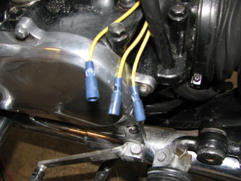
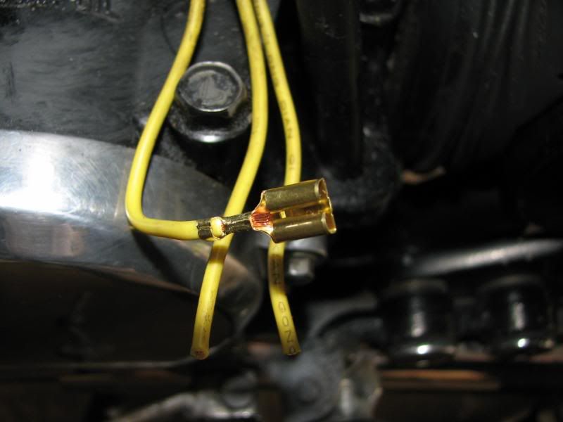
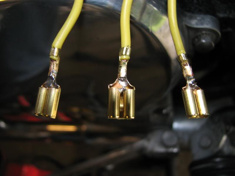
Before I started on the harness install today, I verified the stator performance. I did not get the throttle locked at 5,000 rpm, but I did manage 4,500 rpm. Voltage was 72 VAC on all three pairs. Resistance readings from each lead to ground were all good, as were continuity checks of each lead.

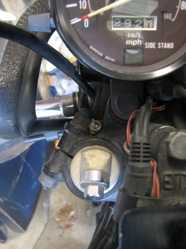
However ... the battery voltage still only gets to upper 13s, even after running for a bit to compensate for the drain of starting the bike. At idle, it will run about 13.0. If the brake light is on, it's about 12.4. At 3,000 rpm (40 mph in fifth gear), it runs about 13.4 volts. Increase speed to 3,500 rpm (48 mph), it rises to about 13.7. Only after running over 4,000 rpm (55 mph) for a while, does it get to 13.9 volts, and slowly drops when the speed is reduced without using the brake light. Yes, it's actually charging the battery, but it's not the "rock-solid 14.4 volts" that others have bragged about.

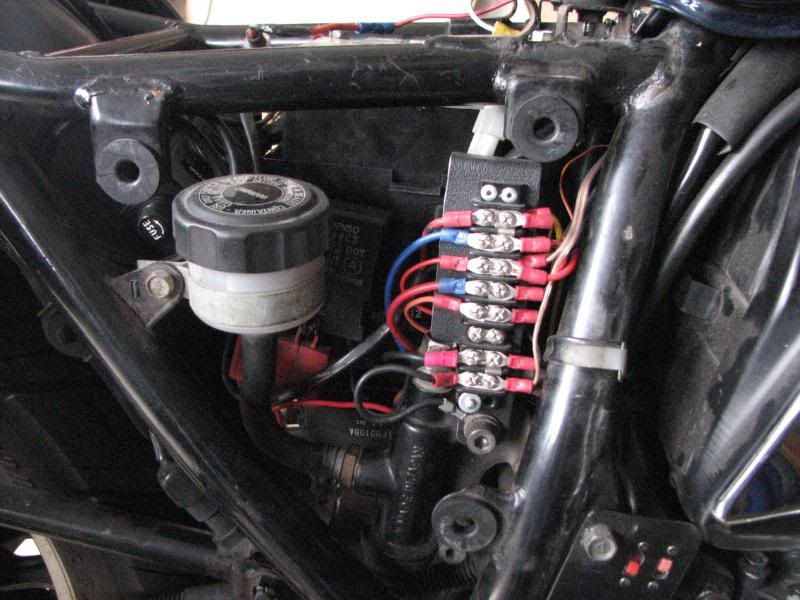
In the course of troubleshooting, I checked the output of the r/r by pulling the fuse to check open-circuit voltage. It's about 15.1. :eek: As soon as I plug the fuse back in to connect the r/r to the battery, it's back down to the upper 12s or lower 13s, depending on engine speed. The only thing I could find that increased the voltage was pulling the headlight fuse. When the voltmeter was reading 13.2, I pulled the headlight fuse and saw 14.3 volts, and this was at about 2,000 rpm. This surprised me a bit, as only the headlight and the instrument lights are on that fuse. I have re-wired the tail light and connected it to the terminal strip powered by the relay, as the tail light was flashing a bit when the headlight modulator was in use. Now that it's powered more or less dirrectly off the battery, it does not flicker nearly as much. Also, to eliminate the possibility that the year-old AGM battery is loading down the system too much, I installed a much-newer (3 months) AGM battery from #2 son's bike. Same results.

I am running out of time here, as I need to pack for my next trip, but it's doing well enough for her to ride to work for the next month while I am gone.

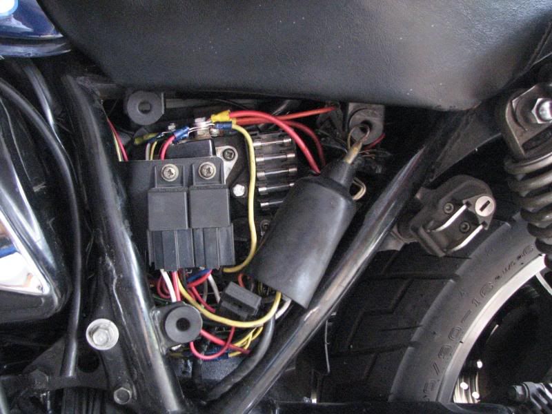
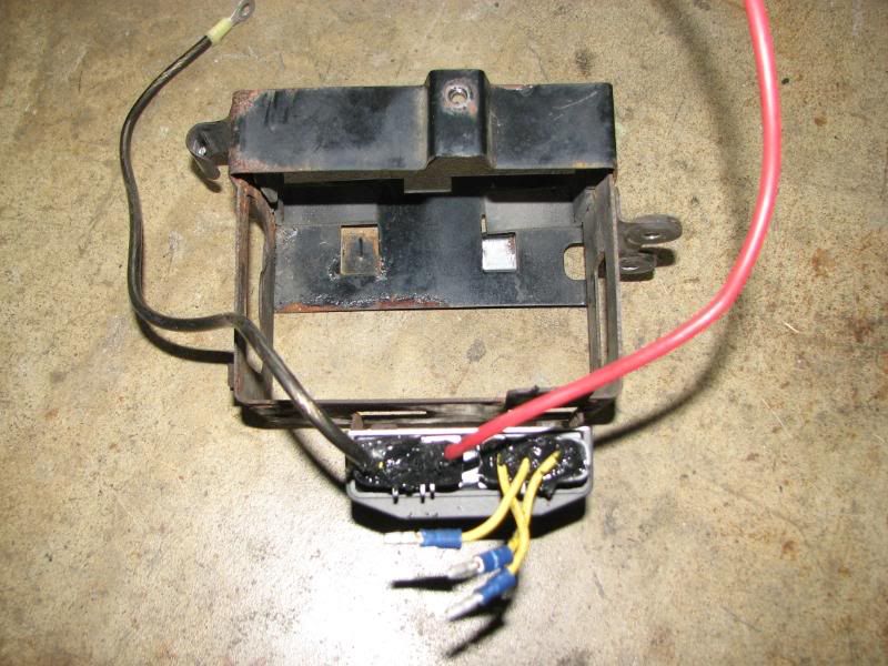
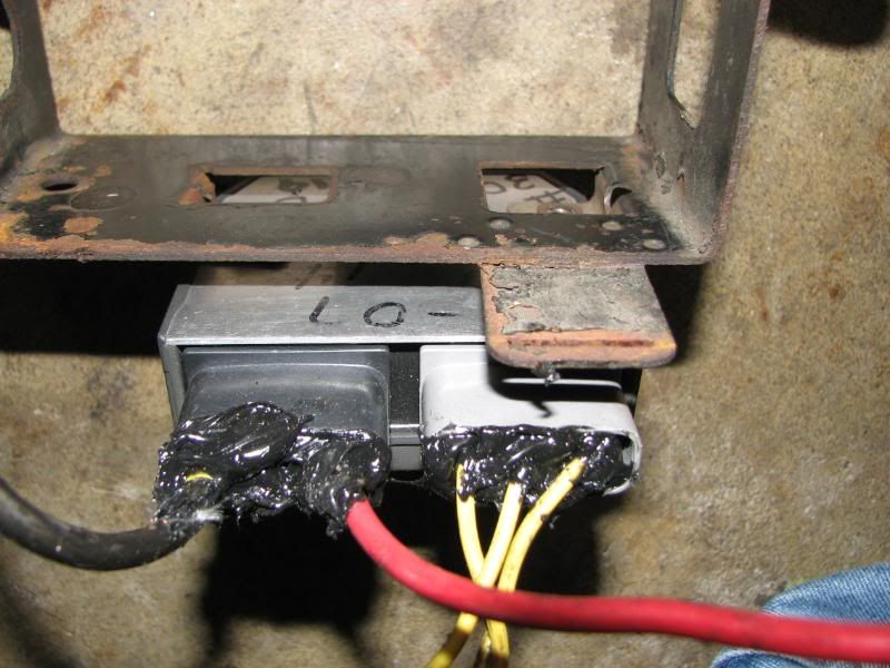
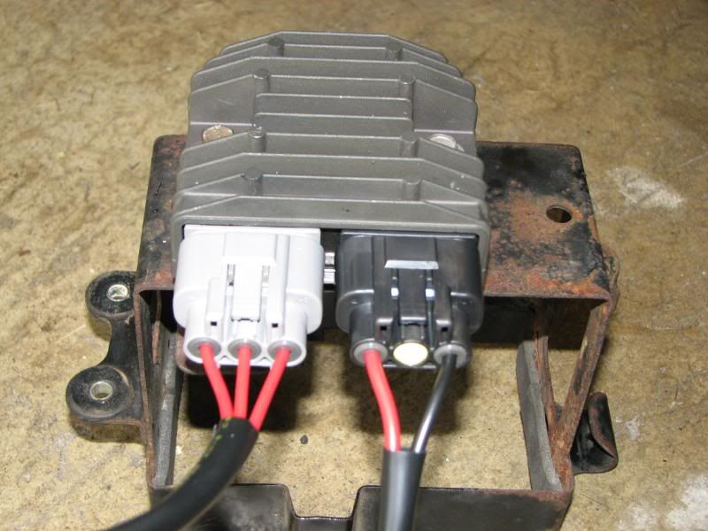
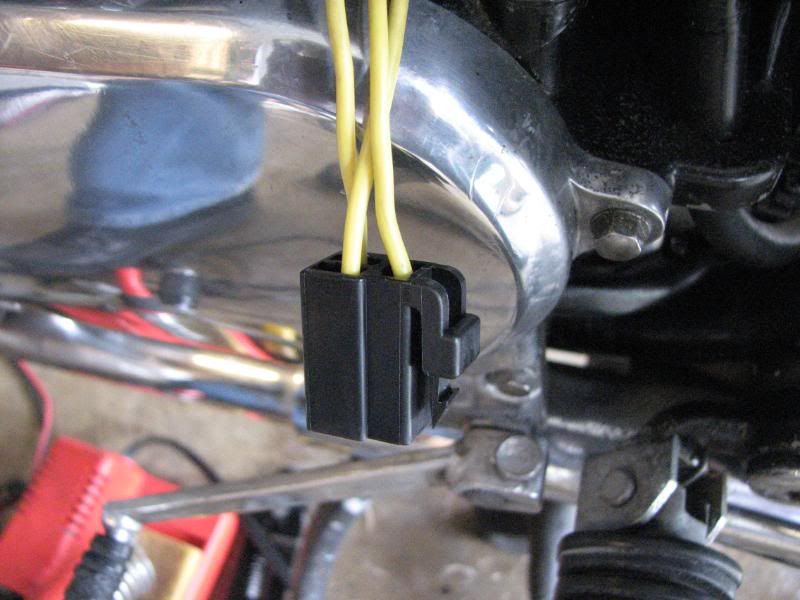
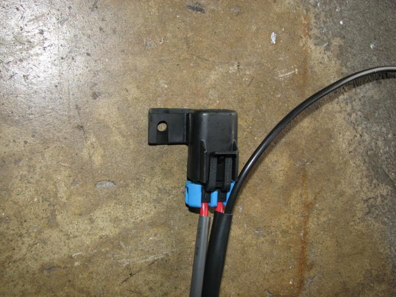
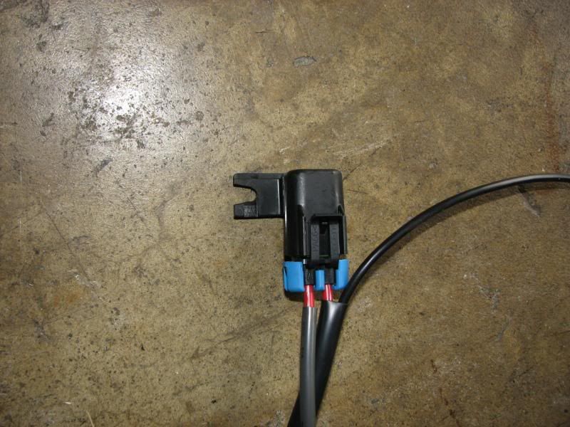
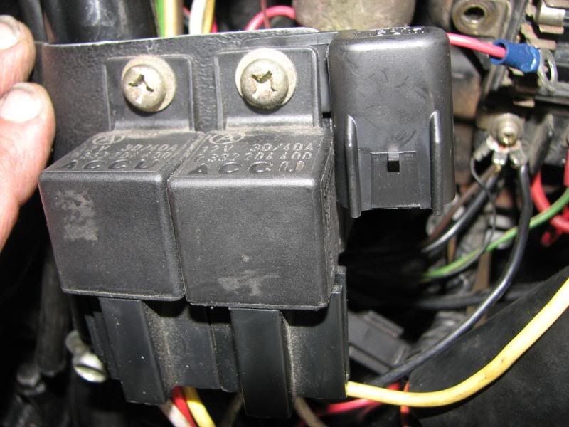
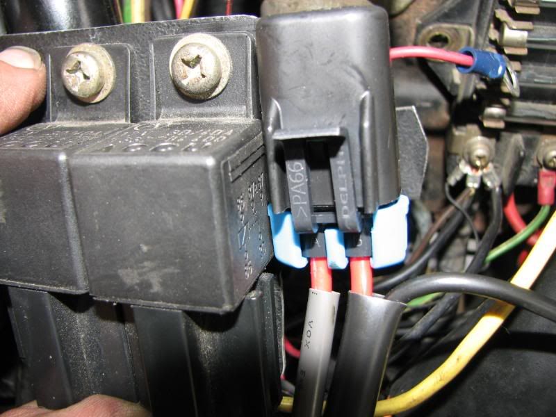
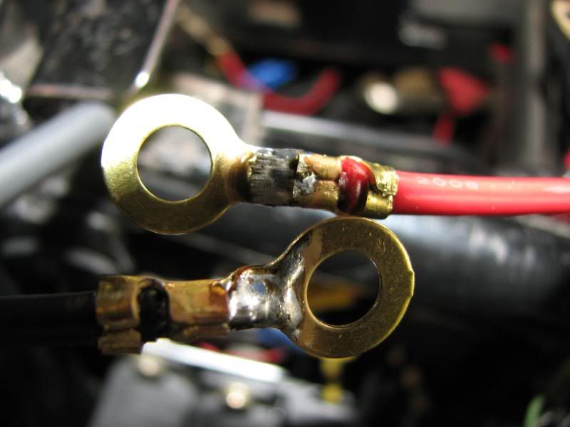
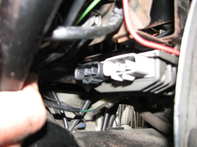
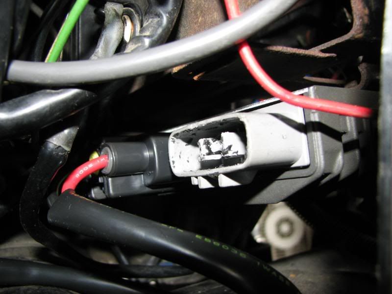
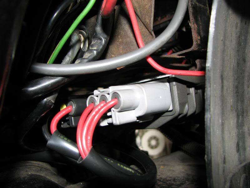
Now, was it worth it? Yes. The harness was $40, but included everything you need to install the FET r/r, and it's a nice, tidy installation. It is helpful to have a good set of crimpers for the uninsulated terminals, but you should already have everything else you need for the install. If you only want the two large connectors that plug into the r/r, they are also available from Eastern Beaver for $20. I just decided to go all-out and get the whole harness.

Your mileage may vary. :D

.
 
Thanks Steve ..

I have one for my 83 (even though the Ricks is working just great).
 
I wonder if you are getting an interraction with that headlight modulator? Got an easy way to bypass the modulator for testing? ... I haven't seen a writeup on the modulator, so don't know anything about it.
Not sure that it's necessary to "bypass" the modulator for testing. :-k

When LOW beam is selected, power goes straight to the headlight. When HIGH beam is selected, the modulator circuit goes into effect, but only if sufficient light is hitting the photosensor. This keeps the modulator from working at night. And ... my lower voltage readings were at the fuses, long before it ever got to the modulator.

"Writeup"? You want a "writeup"? OK, here ya go. :-\\\

Remove headlight from bucket.
Remove connector from back of headlight bulb.
Install modulator on back of headlight bulb.
Connect headlight wiring to back of modulator.
Install photosensor. (hers is mounted near the handlbar mounts, facing UP)
Connect photosensor to modulator.
Put headlight back in bucket.
Verify proper headlight alignment.
Ride, but please use the modulator courteously. (note: before clicking on link, turn down your speakers if you might be offended by what some consider to be 'religious' music. The song is appropriate for a modulator site; it's "I Saw the Light" :D)

Here is a picture of the photosensor. It's the little brass lens-looking thing right in the middle:
IMG_4809.jpg


.
 
I haven't used them [modulators] and didn't know much about them such as disabled when on low beam and the light sensor.
Actually, the Federal Code that allows modulators says that it can be installed in the power wire to either, the high beam or low beam, but can NOT be installed in the ground wire. I think the intent there is to limit its operation to one beam, not both.

The earliest models, the ones that were available back in the 70s, had a switch on them to turn them on and off. To avoid modulator operation at night, the Code now requires a photocell, but does not say anything about also having a switch, too.

The ease of turning the modulator on and off is one thing that makes it so easy to use courteously. When following a car for any length of time, the modulator would be VERY annoying, so I turn it off. When approaching a 4-way stop, I turn it off to prevent other people approaching the sign from thinking I am an emergency vehicle that is going to blast on through. When stopping for any other sign or light, I evaluate the situation. When I am comfortable that there is no danger of anyone pulling out of a driveway or turning in front of me before the sign/signal, I turn it off. Again, the intent of the modulator is to make others aware of my presence, not to annoy them. On the other hand, if a car pulls out in front of me a bit closer than I think would have been prudent (meaning that I had to slow down after they pulled into traffic), I will leave it on in their mirror just to 'remind' them that I am there. :D


.
 
Back
Top