Announcement

Collapse
No announcement yet.

Cam Timing --- GS1100EZ

Collapse
X
 
  • Filter
  • Time
  • Show
Clear All
new posts

    Cam Timing --- GS1100EZ

    I have a question for my 1982 Suzuki GS1100EZ engine.

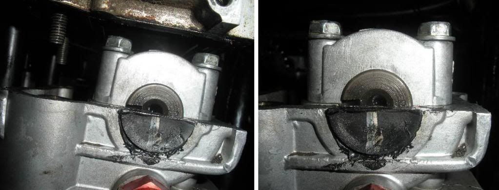
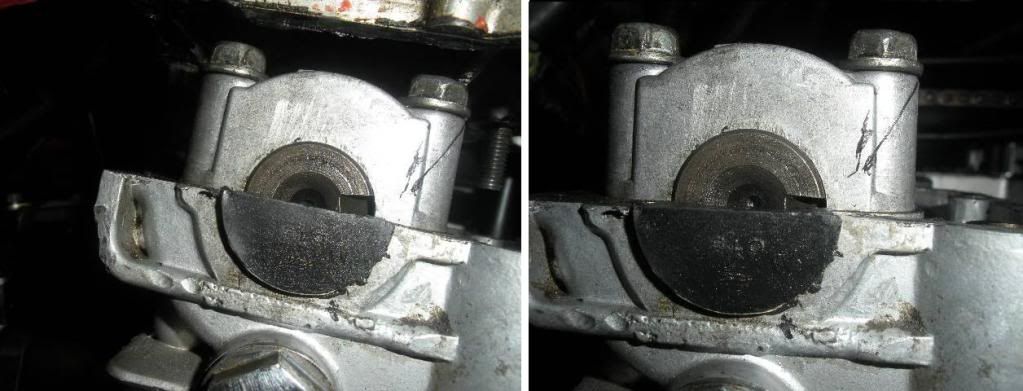
    I can't get this thing timed right. It's always off... The notches at the end of each camshaft do not point directly at each other.

    niclpnut provided this diagram, except it came from a GS1000 manual.


    My bike has a 451 intake camshaft and a 470 exhaust camshaft.


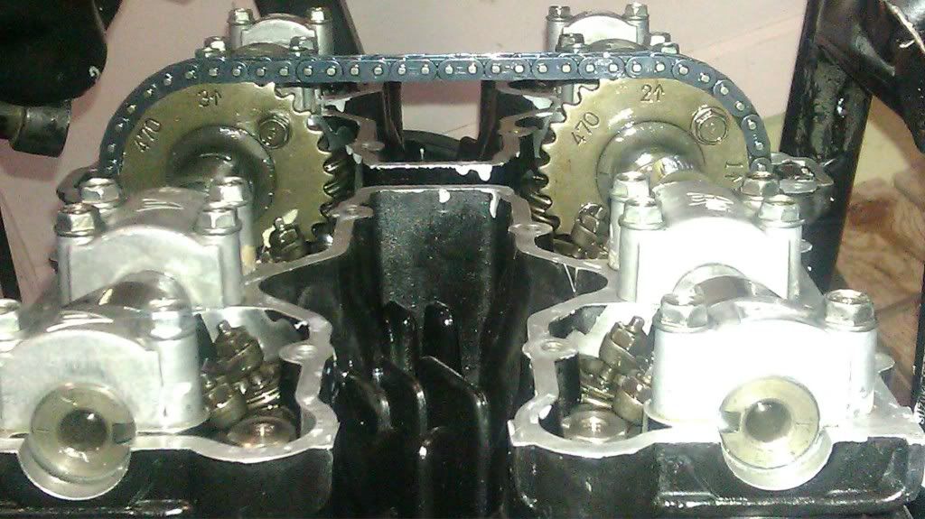
    I did all of my checks when it is aligned with the T mark under the signal generator.


    The picture on the left is with the 20 pin setup. The picture on the right is with the 19 pin setup.

    Exhaust camshaft.


    Intake camshaft.


    20 pin setup.


    19 pin setup.


    As you can see, neither setup has it where the camshaft notches point directly at each other. Why? Could my cams be degreed? Or am I being too anal about this whole thing?

    Please let me know!
    Last edited by Guest; 07-21-2011, 04:51 AM.

    #2
    I think I may have the wrong camshaft sprockets as well. Maybe the 451 and 470 don't mix. From what I've seen, niclpnut has a 470 intake and a 470 exhaust camshaft. John Kat has a 451 intake and 490 exhaust camshaft...

    Comment


      #3
      The numbers on the sprockets don't affect anything here. The slotted cam sprockets DO! You will need to degree the cams correctly to get it to run it's best. If they are stock cams you can just put some stock, not slotted sprockets back on them & install to factory specs. Someone has been in this thing & probably for a reason. Ray.

      Comment


        #4
        Your best bet is to get a dial gauge and degree wheel and slot the sprockets and degree the cams by the book. The bike will run much better.

        Comment


          #5
          Assuming the 1-- mark on the exhaust cam sprocket is properly aligned, I wouldn't worry about being off a little as shown. You won't notice any running problems.
          Ed

          To measure is to know.

          Mikuni O-ring Kits For Sale...https://www.thegsresources.com/_foru...ts#post1703182

          Top Newbie Mistakes thread...http://www.thegsresources.com/_forum...d.php?t=171846

          Carb rebuild tutorial...https://gsarchive.bwringer.com/mtsac...d_Tutorial.pdf

          KZ750E Rebuild Thread...http://www.thegsresources.com/_forum...0-Resurrection

          Comment


            #6
            forget trying to time it by the camshaft end notches.

            the #1 arrow is slightly under the head surface and the arrow for #1 points to the middle of a link plate. (do not have it in between plates)

            the #2 arrow points to the forward pin of a link plate so when counting pins you are on an even number when moving on from plate to plate.

            #3 arrow points at #20 and it is the rearward pin of a link plate..

            turn the engine 720 degrees by hand and recheck alignment.

            done.

            I see by your last photo the exhaust cam is off 1 tooth- the #2 points to the front pin of a link plate, so 19 or 20 gap are both wrong.
            Last edited by trippivot; 07-21-2011, 09:04 AM. Reason: made reference to photo
            SUZUKI , There is no substitute

            Comment


              #7
              Originally posted by trippivot View Post
              forget trying to time it by the camshaft end notches.

              the #1 arrow is slightly under the head surface and the arrow for #1 points to the middle of a link plate. (do not have it in between plates)

              the #2 arrow points to the forward pin of a link plate so when counting pins you are on an even number when moving on from plate to plate.

              #3 arrow points at #20 and it is the rearward pin of a link plate..

              turn the engine 720 degrees by hand and recheck alignment.

              done.

              I see by your last photo the exhaust cam is off 1 tooth- the #2 points to the front pin of a link plate, so 19 or 20 gap are both wrong.
              Yup this.

              The 19 pin set up is for the 1000, you should still set it to 20 pins for the 1100.

              Double check the alignment and look at what pins the arrows point at:


              Should have 10 full links (20 pins arrow to arrow)
              Take another look at yours. See how there are not even links between the arrows?


              Would mean your off a tooth no?

              Look at mine again.


              Nic
              83 GS1100ES rebuild:

              http://www.thegsresources.com/_forum...d.php?t=170032

              Budget GSXR Conversion:

              http://www.thegsresources.com/_forum...d.php?t=200563

              New to me bike: 2008 B-KING

              Comment


                #8
                Originally posted by niclpnut View Post
                ........

                Should have 10 full links (20 pins arrow to arrow)
                Take another look at yours. See how there are not even links between the arrows?


                Would mean your off a tooth no?

                ........ Nic

                If it's full links or not does not matter. You cannot tell how the chain is oriented at the driven sprocket. The chain could have been moved one tooth down there so what he shows is right. The important thing is the timing mark and the pin count separation as well at the relative clocking of the cams.

                But I do hope that when he keeps turning the motor he is doing so in the normal running direction.
                Last edited by Guest; 07-21-2011, 10:30 AM.

                Comment


                  #9
                  Mine never point at each other either.
                  Looks like you have the timing right on the cams. Is the T on your advance on the 1&4 it looks like 2&3 to me?
                  It looks like you have the crank trigger off 90 degrees.
                  Last edited by chef1366; 07-21-2011, 11:02 AM.
                  1983 GS 1100E w/ 1230 kit, .340 lift Web Cams, Ape heavy duty valve springs, 83 1100 head with 1.5mm oversized SS intake valves, 1150 crank, Vance and Hines 1150 SuperHub, Star Racing high volume oil pump gears, 36mm carebs Dynojet stage 3 jet kit, Posplayr's SSPB, Progressive rear shocks and fork springs, Dyna 2000, Dynatek green coils and Vance & Hines 4-1 exhaust.
                  1985 GS1150ES stock with 85 Red E bodywork.

                  Comment


                    #10
                    So could this be a worn out timing chain? There is a stretch test is there not?

                    Comment


                      #11
                      Originally posted by chef1366 View Post
                      Mine never point at each other either.
                      Looks like you have the timing right on the cams. Is the T on your advance on the 1&4 it looks like 2&3 to me?
                      It looks like you have the crank trigger off 90 degrees.
                      My crank trigger is also off? Damn....

                      The #1 arrow points between the plates. Bad right?


                      I will try again. I am rotating the engine by hand in the clockwise direction. I never went counter clockwise.

                      Comment


                        #12
                        The pickup plate appears to be on upside down as per the photos in the manual.

                        That would certainly cause issues.

                        Comment


                          #13
                          Originally posted by JEEPRUSTY View Post
                          The pickup plate appears to be on upside down as per the photos in the manual.

                          That would certainly cause issues.
                          The pickup plate is the thin metal thing under the signal generator, right? I thought it could only go on one way.

                          Comment


                            #14
                            Originally posted by Flaming Chainsaws View Post
                            The pickup plate is the thin metal thing under the signal generator, right? I thought it could only go on one way.

                            It should I suppose.
                            It shows it as having a tab at the top in the photos.
                            It goes into the semi circle just above the screw.
                            Whats it look like on the bottom?

                            Comment


                              #15
                              Jesus I am stupid sorry.
                              Had no idea what the bottom half looked like.
                              Yes it only goes on one way.

                              I am going to stop "helping" now as I am only causing alarm.

                              My bike has a little leeway ( for want of a better term ) int eh notch alignment as well.
                              I attributed it to shcain wear.
                              Bike ran fine though until the igniter died.

                              If everything is aligned as one of the prev posters staates then check you clearances.

                              Comment

                              Working...
                              X