Announcement

Collapse
No announcement yet.

Timing Problem - GS850

Collapse
X
 
  • Filter
  • Time
  • Show
Clear All
new posts

    Timing Problem - GS850

    Just about finished with re-building my motor (new rings, lapped valves, new cam chain) and Im running into an issue while trying to get the mechanical timing right. The exhaust cam seems to be in the correct position but the intake cam looks like a degree or so out. I made to sure count 20 pins between the 2 and 3 arrows, and its was to little of a difference for it to be off by a link (I tried). When I look, the the arrows they look pretty much right (1 point directly forward, 2 points straight up, and three points one pin off from straight up) but the rectangular notches are not in line with one another. I have also checked the idler and there is no play and seems to be in great condition. Does anyone know what could cause this?

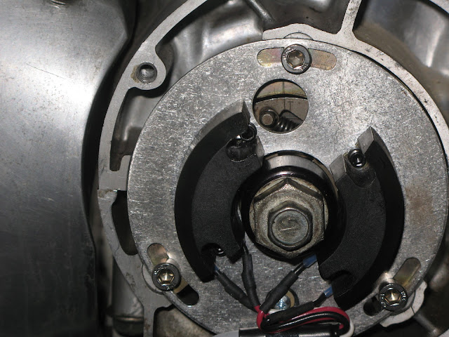
    I have included pictures of everything, Let me know if there is any more info or picture that could help.


    #2
    Timing looks good. Don't worry about the notches.
    Ed

    To measure is to know.

    Mikuni O-ring Kits For Sale...https://www.thegsresources.com/_foru...ts#post1703182

    Top Newbie Mistakes thread...http://www.thegsresources.com/_forum...d.php?t=171846

    Carb rebuild tutorial...https://gsarchive.bwringer.com/mtsac...d_Tutorial.pdf

    KZ750E Rebuild Thread...http://www.thegsresources.com/_forum...0-Resurrection

    Comment


      #3
      Cool thanks, now is that because the notches dont really matter?

      Comment


        #4
        Originally posted by Lunchbox88 View Post
        Cool thanks, now is that because the notches dont really matter?
        The notches are there more for a quick visual "sanity check" -- they're a bit approximate. The "T" mark and the marks on the camshaft sprockets are the important parts.

        Looks fine to me, too. Button 'er up!


        Great pics, too!


        (What happened to that poor acorn nut in the fourth photo?)
        1983 GS850G, Cosmos Blue.
        2005 KLR685, Aztec Pink - Turd II.3, the ReReReTurdening
        2015 Yamaha FJ-09, Magma Red Power Corrupts...
        Eat more venison.

        Please provide details. The GSR Hive Mind is nearly omniscient, but not yet clairvoyant.

        Celeriter equita, converteque saepe.

        SUPPORT THIS SITE! DONATE TODAY!

        Co-host of "The Riding Obsession" sport-touring motorcycling podcast at tro.bike!

        Comment


          #5
          Originally posted by bwringer View Post
          The notches are there more for a quick visual "sanity check" -- they're a bit approximate. The "T" mark and the marks on the camshaft sprockets are the important parts.

          Looks fine to me, too. Button 'er up!


          Great pics, too!


          (What happened to that poor acorn nut in the fourth photo?)
          Thanks, I figured pictures would help more than me just trying to explain it with text.

          And that acorn nut was mutilated by a PO unfortunately. Looks rough but has good threads and still fits well in the socket so I just kept it.

          Thanks for the answers guys it put my mind to ease for sure.

          Comment


            #6
            Just to make sure you don't make the same mistake that I did (several times), ... when you say you have "20 pins between the 2 and 3 arrows", are you counting the pins that are over the arrows? The mistake that I kept making was essentially calling the pin over the #2, "ZERO", making "ONE" then next one over. The one over the #2 should be "ONE", making the next one over "TWO". I kept getting it one tooth off by doing that. Because the pins over the #2 and the #3 are counted, technically, there are only 18 pins between the two arrows.

            By the way, it's hard to count the pins with the idler on there, but you have to remove the carbs to remove and reset the cam chain tensioner if you remove it, so I hope you counted pins before putting the idler in place.

            .
            sigpic
            mine: 2000 Honda GoldWing GL1500SE and 1980 GS850G'K' "Junior"
            hers: 1982 GS850GL - "Angel" and 1969 Suzuki T250 Scrambler
            #1 son: 1986 Yamaha Venture Royale 1300 and 1982 GS650GL "Rat Bagger"
            #2 son: 1980 GS1000G
            Family Portrait
            Siblings and Spouses
            Mom's first ride
            Want a copy of my valve adjust spreadsheet for your 2-valve per cylinder engine? Send me an e-mail request (not a PM)
            (Click on my username in the upper-left corner for e-mail info.)

            Comment


              #7
              Originally posted by Steve View Post
              Just to make sure you don't make the same mistake that I did (several times), ... when you say you have "20 pins between the 2 and 3 arrows", are you counting the pins that are over the arrows? The mistake that I kept making was essentially calling the pin over the #2, "ZERO", making "ONE" then next one over. The one over the #2 should be "ONE", making the next one over "TWO". I kept getting it one tooth off by doing that. Because the pins over the #2 and the #3 are counted, technically, there are only 18 pins between the two arrows.

              By the way, it's hard to count the pins with the idler on there, but you have to remove the carbs to remove and reset the cam chain tensioner if you remove it, so I hope you counted pins before putting the idler in place.

              .
              I did in fact count the pins above arrows 2 and 3, but that's for the heads up, thats something I could have easily looked over. Also the idler was out when I counted and the tensioner has been reset so I should be good there.

              Again thanks for quick replies and answers, Im sure I would still be cursing at my valve train now with out them.

              Comment


                #8
                It has to be an even number of pins in the photo. If the #2 is pointing to the first pin of the outer plate of the chain and the #3 is pointing to the second pin of the outer plate then there is an even number of pins between the arrows. It is correct at 20. The notches in the end of the cams would be out of alignment more than they are if was even off by one tooth.

                Comment


                  #9
                  Originally posted by TeamDar View Post
                  It has to be an even number of pins in the photo. If the #2 is pointing to the first pin of the outer plate of the chain and the #3 is pointing to the second pin of the outer plate then there is an even number of pins between the arrows. It is correct at 20. The notches in the end of the cams would be out of alignment more than they are if was even off by one tooth.
                  Good point - you are right. It can only be 18 or 20. And it's not 18!
                  79 GS1000S
                  79 GS1000S (another one)
                  80 GSX750
                  80 GS550
                  80 CB650 cafe racer
                  75 PC50 - the one with OHV and pedals...
                  75 TS100 - being ridden (suicidally) by my father

                  Comment

                  Working...
                  X