Announcement

Collapse
No announcement yet.

Help me wire these switches on my GS1000

Collapse
X
 
  • Filter
  • Time
  • Show
Clear All
new posts

    Help me wire these switches on my GS1000

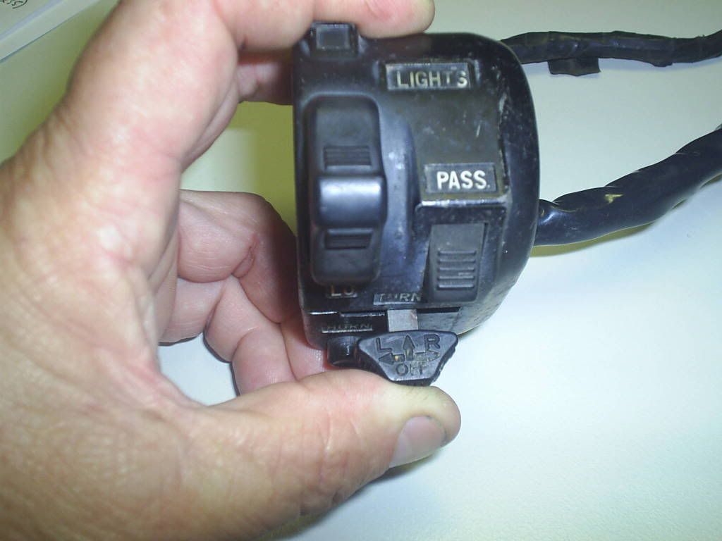
    I bought some bar controls off of MikesXS for my cafe project and now I need to wire them in. These are the switches in question:

    Right side:


    Left side:


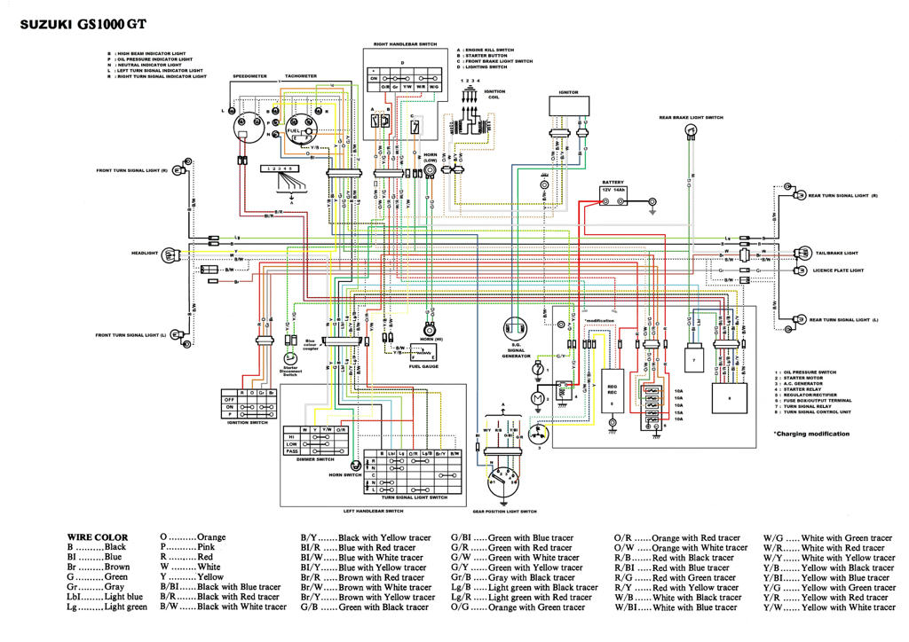
    I emailed MikesXS and was told that this is the wiring diagram to follow:


    GS1000 wiring diagram:


    How do I wire these in? Ive looked at the diagrams quick but unsure exactly how to splice everything together and make sure everything works. What type of connectors should I use to mate the switch harness with my stock harness? Id like to use new connectors but cant find anything local with enough pins. Do I have to buy on line?
    Last edited by Guest; 03-25-2011, 09:35 AM.

    #2
    Originally posted by DrImodium View Post
    I bought some bar controls off of MikesXS for my cafe project and now I need to wire them in. These are the switches in question:

    Right side:


    Left side:


    I emailed MikesXS and was told that this is the wiring diagram to follow:


    Here are the diagrams for my 78 GS1000

    Left side:


    Right side:


    How do I wire these in? Ive looked at the diagrams quick but unsure exactly how to splice everything together and make sure everything works. What type of connectors should I use to mate the switch harness with my stock harness? Id like to use new connectors but cant find anything local with enough pins. Do I have to buy on line?
    Here is a start. The two columns show one for one matchups but check the comment because some are in question. The starter button looks like it wants to do a lowside control of the solenoid. That might be a little tricky. You will have to make your solenoid low side control. Also the head lamp switch are dual ganged switches so not sure why unless it is for current carrying split between headlamp and tail light.
    Last edited by posplayr; 06-27-2010, 12:35 PM.

    Comment


      #3
      Do you have the original switches? If so, I'd snip off the the connectors leaving a couple of inches of wires attached and then solder them to the wires on the new switches. It shouldn't be hard to match up the wires. Get yourself some heat shrink tubing for after the wires are soldered and you should be good to go.
      Ed

      To measure is to know.

      Mikuni O-ring Kits For Sale...https://www.thegsresources.com/_foru...ts#post1703182

      Top Newbie Mistakes thread...http://www.thegsresources.com/_forum...d.php?t=171846

      Carb rebuild tutorial...https://gsarchive.bwringer.com/mtsac...d_Tutorial.pdf

      KZ750E Rebuild Thread...http://www.thegsresources.com/_forum...0-Resurrection

      Comment


        #4
        I Have The Same Left Hand Switch

        I have the same left hand switch, so if you have any specific questions as to wiring it up then let fly. I didn't like the idea of jointed wires in length so I opened the Yamaha switch and soldererd the GS wires (I had a good condition 12 pin plug and switch wiring) in place of the Yamaha ones inside the switch. Be careful with the half circle brass strip.

        Comment


          #5
          On your wiring diagram for the 1000 you are missing the internal power wire from the ON/OFF switch to the DIMMER switch. On the new setup you need to run this power wire from the RH switch to the LH switch.

          If you plan to use the passing switch (which I believe was not an option in the U.S.) there needs to be additional wiring coming from the RH switch to the LH switch for that as well. If you are going to proceed with that option then you would need an Australian, UK, Europe, etc. wiring diagram. I can fix you up with one if you need it.

          Also note that the internal earth for the horn is a different set up on the Yamaha switch than on the Suzuki one. The Suzuki switch body is plastic and inferior to the Yamaha alloy switch body. Also the Yamaha switch has a much more sturdy choke setup on it than on the Suzuki, although with your model 1000 with VMs it will not make any difference.

          Comment


            #6
            Originally posted by posplayr View Post
            The starter button looks like it wants to do a lowside control of the solenoid. That might be a little tricky. You will have to make your solenoid low side control.
            What does this mean? How do I fix this issue?


            Originally posted by posplayr View Post
            Also the head lamp switch are dual ganged switches so not sure why unless it is for current carrying split between headlamp and tail light.
            Again, what does this mean?

            Sorry for the newb questions

            Comment


              #7
              Originally posted by Suzuki_Don View Post
              On your wiring diagram for the 1000 you are missing the internal power wire from the ON/OFF switch to the DIMMER switch. On the new setup you need to run this power wire from the RH switch to the LH switch.

              If you plan to use the passing switch (which I believe was not an option in the U.S.) there needs to be additional wiring coming from the RH switch to the LH switch for that as well. If you are going to proceed with that option then you would need an Australian, UK, Europe, etc. wiring diagram. I can fix you up with one if you need it.

              Also note that the internal earth for the horn is a different set up on the Yamaha switch than on the Suzuki one. The Suzuki switch body is plastic and inferior to the Yamaha alloy switch body. Also the Yamaha switch has a much more sturdy choke setup on it than on the Suzuki, although with your model 1000 with VMs it will not make any difference.
              Don,
              What is the Passing switch? Is that the same as the dimmer?
              Jim

              Comment


                #8
                Originally posted by DrImodium View Post
                What does this mean? How do I fix this issue?


                Again, what does this mean?

                Sorry for the newb questions
                If you look at your new switch control for start in ON position it connects the L/W to ground. Otherwise when OFF it is all NO CONNECT That means it is doing low side control of the solenoid.

                Low side means you power a device from +12V for example but you control on/off by grounding or removing the ground.

                Most OEM solenoids use high side control (theones I have seen). The Green/Yellow wire to your solenoid is connected to +12V when the start button in ON position . So you will need a solenoid with two wires to it. Connect +12V to one side and run the ground back to your switch which will ground the wire when the button is pushed.

                Under Lights when in ON position the R/Y is connected to both L/B and L. L/B and L are for two seperate circuits related to headlights. Lights is one, maybe the other is for stator loop control.

                Comment


                  #9
                  solder and shrink wrap. or K&L has up to 9 pin plug male and female just like stock-- special square crimpers needed.
                  SUZUKI , There is no substitute

                  Comment


                    #10
                    Originally posted by posplayr View Post
                    Don,
                    What is the Passing switch? Is that the same as the dimmer?
                    Jim
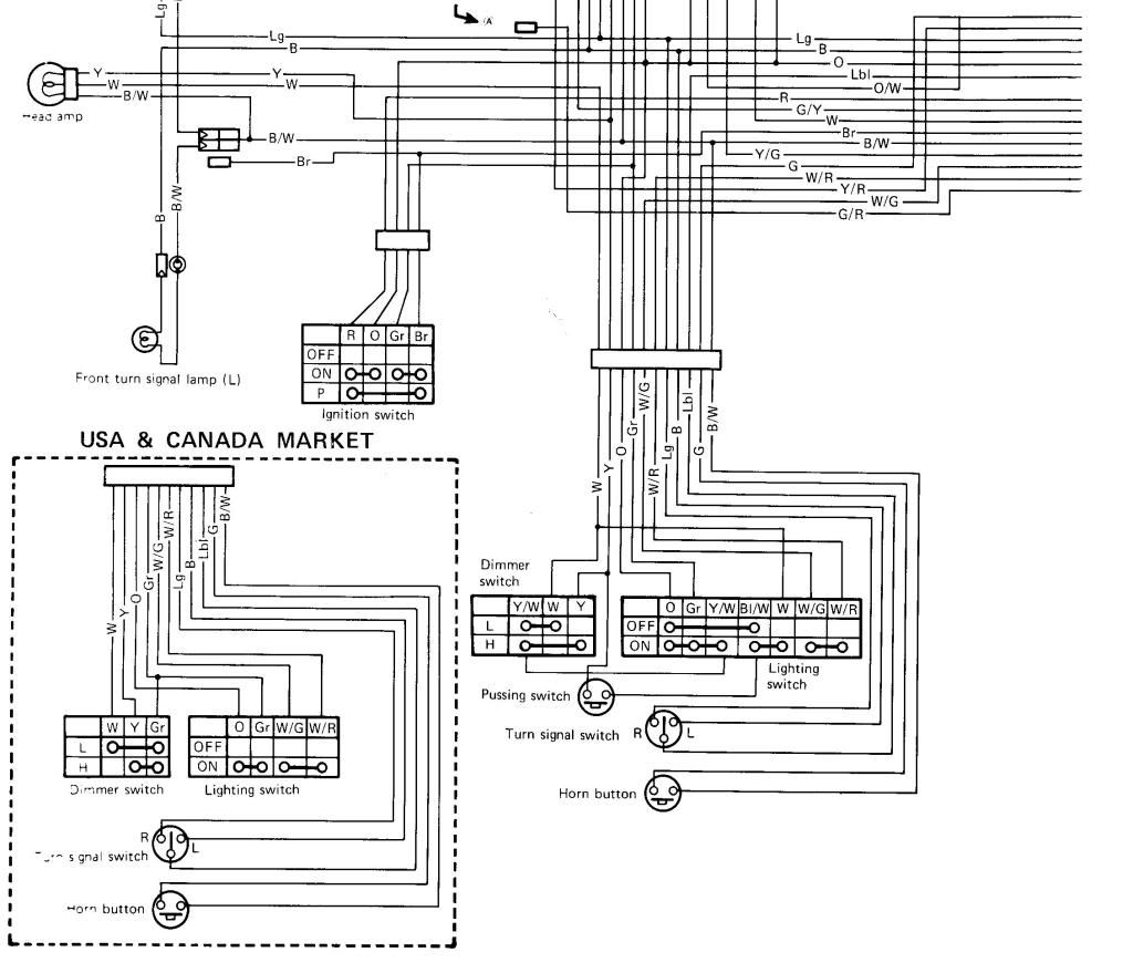
                    Jim, I'm afraid I have made a grave mistake. I thought the switchgear in question on the LH side was the same as the one that I am using. It is very similar, but not the same. My switchgear is from an XJ650 and the switchgear in Post #1 is new and from an XS650 twin. It does not have the passing switch as does my Australian model switchgear.


                    The Australian GS models and I believe the UK and European models had a passing switch fitted. It is the type of switch that can be used for flashing vehicles coming in the opposite direction, etc. The same as in a car type switch to flash other vehicles. You can see the pass button on the picture above. I will include a wiring diagram for more clarity off my '77 GS550. You will also see the Japanese cannot spell very well, spelling PASSING as "PUSSING". You will see the passing switch just above the horn and turn signal switches.

                    You will also see the USA and Canada market had a different option (less option) than the rest of the world.


                    Last edited by Guest; 06-30-2010, 08:17 PM.

                    Comment

                    Working...
                    X