Announcement

Collapse
No announcement yet.

Forward Mounted R/R, Where to Connect It To!!!

Collapse
X
 
  • Filter
  • Time
  • Show
Clear All
new posts

    Forward Mounted R/R, Where to Connect It To!!!

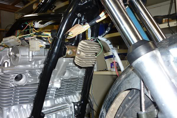
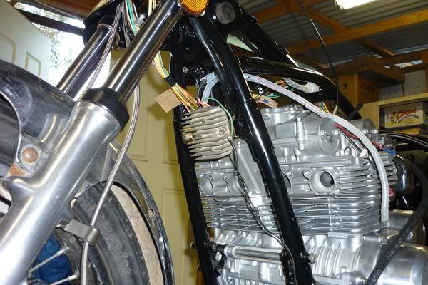
    I have mounted the Honda R/R on the front down tubes of the frame, but up high just under the triple tree. The nearest point to pick up the red wire for the active charging system back to the battery is the red wire going to the ignition switch from the solenoid. Can anyone see a problem with connecting the red wire from the R/R to the red wire from the ign switch in the headlight bucket. Is it too far from the battery for good charging?

    BTW I have 15 amp red wire from solenoid to ign switch and 15 amp orange wire from ign switch to ganged fuses, up from 10 amp wire original.

    What are your thoughts?

    #2
    Don,
    I would really perfer short distances to the battery with a minimum of connections. What model R/R are you using?The ultimate test will be if you can get low voltage drops as per the stator pages.
    Jim

    Comment


      #3
      Jim, It's the Honda unit as supplied by Duane -- SH532 - 12 (6 wire).

      Comment


        #4
        Originally posted by Suzuki_Don View Post
        BTW I have 15 amp red wire from solenoid to ign switch and 15 amp orange wire from ign switch to ganged fuses, up from 10 amp wire original.

        What are your thoughts?
        rather than to say move the R/R back to the stock location. If you have a 15 amp Red from the solenoid which is live battery the connect to that.

        If you study the fusing in my simplified drawings, suzuki runs a fuze between the battery and R/R. Then after running forward .......in your 15Amp red it returns back to the fuse box. So it sounds like you need a fuse inline between the solenoid and switch . But a simple picture would belp. It is hard enough trying to visualize the connections but doing a FMEA is very dicy

        Comment


          #5
          Jim I guess I over-simplified my description. When I said I had a 15 amp Red wire running from the solenoid to the Ign Sw. I actually meant (and I know you are not a mind reader) The standard Red wire from solenoid to one side of fuse then my 15 amp Red wire runs from the other side of that fuse to the ignition switch. My plan was to tap into this wire either in the headlamp bucket or a bit further back under the fuel tank.

          Do You think that would work OK.

          The reason that I cannot fit the R/R in it's normal position (keeping in mind my bike originally had a rectifier and separate regulator) is that I have fitted a 6-Way fuse box in place of the original in-line fuse (one and only). So no room for the larger R/R to fit in this area.


          Last edited by Guest; 07-04-2010, 07:45 AM.

          Comment


            #6
            Originally posted by Suzuki_Don View Post
            Jim I guess I over-simplified my description. When I said I had a 15 amp Red wire running from the solenoid to the Ign Sw. I actually meant (and I know you are not a mind reader) The standard Red wire from solenoid to one side of fuse then my 15 amp Red wire runs from the other side of that fuse to the ignition switch. My plan was to tap into this wire either in the headlamp bucket or a bit further back under the fuel tank.

            I did this Bobber schematic a while back; It is about a simple as I could make it while maintaining basic safety considerations. It sounds lke your R/R to Battery connections have a single fuse between as shown. And so your real question is if you move the "T" (the point that splits the R/R output going to ignition switch and to the primary fuse) all the way forward to the ignition switch. Electrically it is identical. The only issue would be the extra length of wire which your have uprated from 10 to 15 amp wire. So that would be OK.

            Next question are you running your harness and battery grounds forward to the R/R as well?

            Technical Info posts that are deemed to be important or popular will be placed here for easier access. If you feel a post should be moved from the Technical Info forum to here then PM the Administrator with your request.


            Comment


              #7
              I am using an earth bar (brass) adjacent to the battery and intend to run all earth (ground) wires back to there including the one from the R/R, battery -ive, loom lugs and engine earth, plus any others that pop up while I am doing the rewire.

              BTW I have increased the size of the main earth wire in the loom to 15 amp wire. Some of the tails off the main earth are still 10 amp although the two tails that go to the battery box and solenoid mounting screw are both 15 amp as well as the earth from the R/R back to the battery (earth bar) is 15 amp as well.

              The earth bar can take six earth strap lugs and this fits with your single mounting ground point, I think.

              Any thoughts.

              Comment


                #8
                Originally posted by Suzuki_Don View Post
                The earth bar can take six earth strap lugs and this fits with your single mounting ground point, I think.

                Any thoughts.
                When I say single point ground it is not just anywhere. It is at the point of lowest voltage where all ground currents return. That would be the R/R (-). Just make sure there is very little voltage drop from R/R(-) to the battery(-) and you should be OK. 15 amp wire to the R/R (-) from the earth bar, and 15 amp from battery to earth bar.

                Comment


                  #9
                  Originally posted by posplayr View Post
                  When I say single point ground it is not just anywhere. It is at the point of lowest voltage where all ground currents return. That would be the R/R (-). Just make sure there is very little voltage drop from R/R(-) to the battery(-) and you should be OK. 15 amp wire to the R/R (-) from the earth bar, and 15 amp from battery to earth bar.
                  Thanks Jim.

                  How do I measure the voltage drop on the negative side as you have stated above.

                  Comment


                    #10
                    Originally posted by Suzuki_Don View Post
                    Thanks Jim.

                    How do I measure the voltage drop on the negative side as you have stated above.

                    this way..............

                    Finally STEP #3.) Perform Stator Paper Checks. The stator pages checks are not perfect, but they are designed to help you through a process of elimination in determining what is wrong with your charging system. The good news about doing steps #1 and #2 above first, is that when the stator pages say to check your connections you know you already have done it. Here is the update.


                    http://www.thegsresources.com/statorpapers4.php

                    Link to Revised PHASE A of Stator Pages:

                    Last edited by posplayr; 11-16-2015, 07:36 PM.

                    Comment


                      #11
                      Thanks Jim, I guess I will have to wait till the motor is running to do that test. Eh.

                      Thanks again.

                      Comment

                      Working...
                      X