.png "Powered by vBulletin")
Hello Good People! i need some help with my Coil Relay Mod.. It seems very simple but i am confused on what to do with what seems like extra wires..
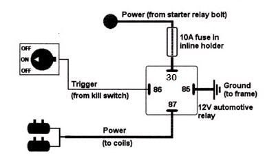
Here is what i know with the Relay
30- Direct Power from the + On the Battery /w Inline Fuse
85- Ground
86- ??
87- The orange wires comming directly from the coils
I know 86 says it should get wires from the switch but i am confused, There are 3 wires comming from the right handlebar switch.. 2 orange and one Green :
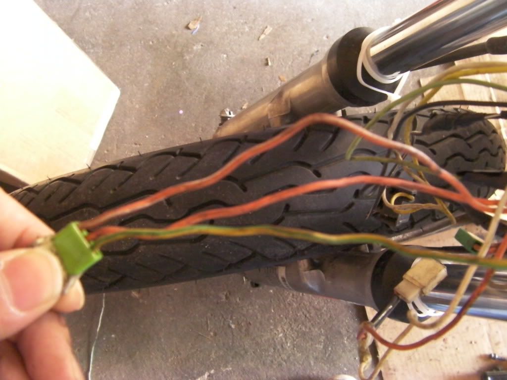
Im Guessing i should solder the two orange wires together put a female connector and hook it up too 86? the green wire goes to wherever it used to go? or do i solder all three?
Also guys i am stuck here with the solenoid.... shouldnt one of these wires goto the relay?
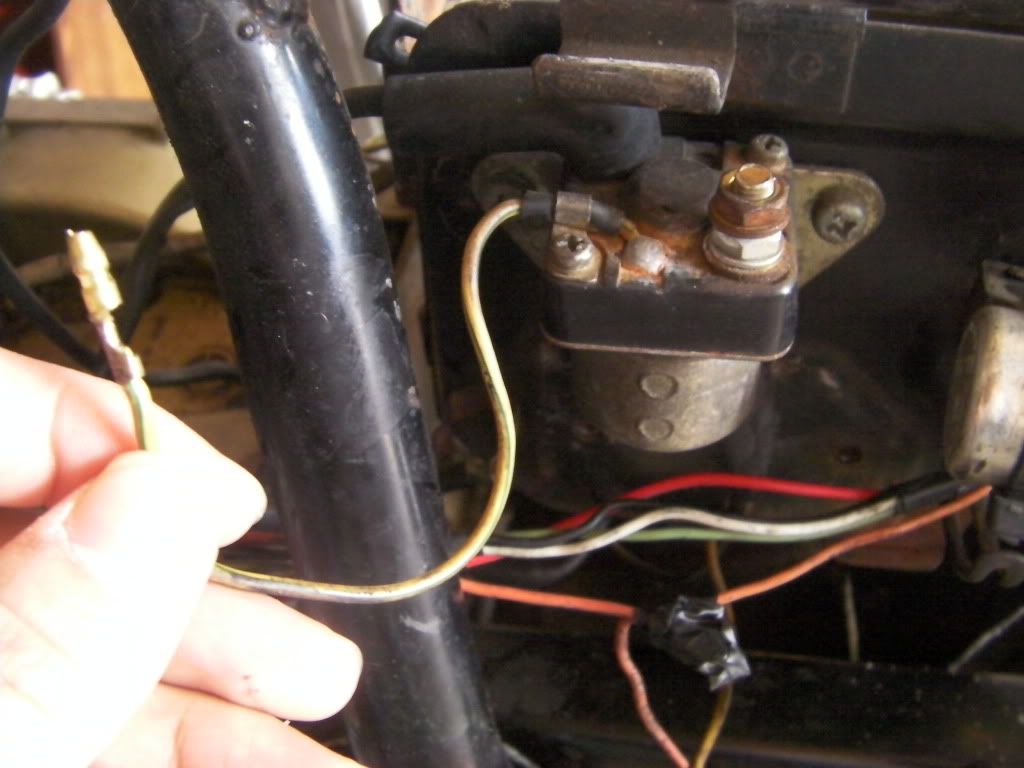
I am confused at where the wire in my hand goes to... and do i need to route a power wire from the nut to the + battery like there used to be?
also guys i know this may seem a bit much but i dont know where this wire goes to, It comes out of the metal heat sink thing mounted on the bottom of the battery bracket..
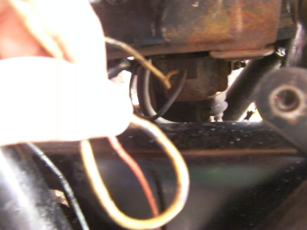
thanks guys... i really want to tackle this today but i am just stuck..
Here is what i know with the Relay
30- Direct Power from the + On the Battery /w Inline Fuse
85- Ground
86- ??
87- The orange wires comming directly from the coils
I know 86 says it should get wires from the switch but i am confused, There are 3 wires comming from the right handlebar switch.. 2 orange and one Green :
Im Guessing i should solder the two orange wires together put a female connector and hook it up too 86? the green wire goes to wherever it used to go? or do i solder all three?
Also guys i am stuck here with the solenoid.... shouldnt one of these wires goto the relay?
I am confused at where the wire in my hand goes to... and do i need to route a power wire from the nut to the + battery like there used to be?
also guys i know this may seem a bit much but i dont know where this wire goes to, It comes out of the metal heat sink thing mounted on the bottom of the battery bracket..
thanks guys... i really want to tackle this today but i am just stuck..

Comment