Announcement

Collapse
No announcement yet.

duaneage Honda R/R Question

Collapse
X
 
  • Filter
  • Time
  • Show
Clear All
new posts

    #46
    Hi,

    Most r/r output wires are red. Find your r/r unit and trace the wire to where it connects into the harness. Replace all of the bullet connectors in your charging system.


    For reference:
    Regulator/Rectifier Replacement


    Thank you for your indulgence,

    BassCliff

    Comment


      #47
      Originally posted by BassCliff View Post
      Hi,

      Most r/r output wires are red. Find your r/r unit and trace the wire to where it connects into the harness. Replace all of the bullet connectors in your charging system

      BassCliff
      That pic is going to confuse him with two greens and two reds- he'll feel cheated!

      To Legionnaire; It's best to heed Basscliff's cleanup the connections advice, but as a temporary check, you can connect the R/R sense wire direct to battery positive and see what your voltage outputs are at idle and at 4k rpm
      1981 gs650L

      "We are all born ignorant, but you have to work hard to stay stupid" Ben Franklin

      Comment


        #48
        After all this I seem to be even more confused, so I just replaced my stock R/R with a Honda r/r all the connections are new. What I am most confused about is where you guys are telling me where to check for loss, cause in the photo above I put my positive lead on the battery and the negative on the sense wire and it was almost the same voltage and then I turned the bikes electrical on and it dropped to .8 does that mean anything or is that not the right stuff to test.

        If someone could tell me exactly what to test that would be great because you guys are really helpful but the way you have things worded at the moment for some reason is over my head. Just tell me where to put my voltmeter and i will be a very gracious man thank you all so much!!!


        Originally posted by BassCliff View Post
        Hi,

        Most r/r output wires are red. Find your r/r unit and trace the wire to where it connects into the harness. Replace all of the bullet connectors in your charging system.


        For reference:
        Regulator/Rectifier Replacement


        Thank you for your indulgence,

        BassCliff

        Comment


          #49
          Originally posted by tom203 View Post
          That pic is going to confuse him with two greens and two reds- he'll feel cheated!

          To Legionnaire; It's best to heed Basscliff's cleanup the connections advice, but as a temporary check, you can connect the R/R sense wire direct to battery positive and see what your voltage outputs are at idle and at 4k rpm
          This makes sense now haha so I'm basically skipping the orange wire and if my outputs are good than the orange wire is the culprit. Got it!!

          Comment


            #50
            Hi,

            Check your wiring diagram. An orange wire is usually a switched 12v wire (powered when the key is on). In your picture I can't tell which wires are going where. As for the r/r and stator connectors, this is the standard diagram.


            You want to check the voltage loss between the r/r output and the battery (+).


            Thank you for your indulgence,

            BassCliff

            Comment


              #51
              Originally posted by BassCliff View Post
              Hi,

              Check your wiring diagram. An orange wire is usually a switched 12v wire (powered when the key is on). In your picture I can't tell which wires are going where. As for the r/r and stator connectors, this is the standard diagram.


              You want to check the voltage loss between the r/r output and the battery (+).


              Thank you for your indulgence,

              BassCliff
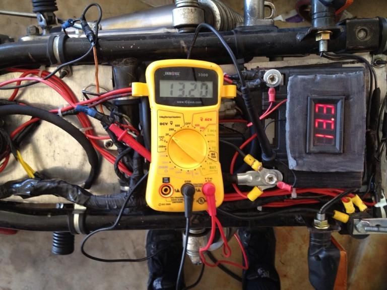
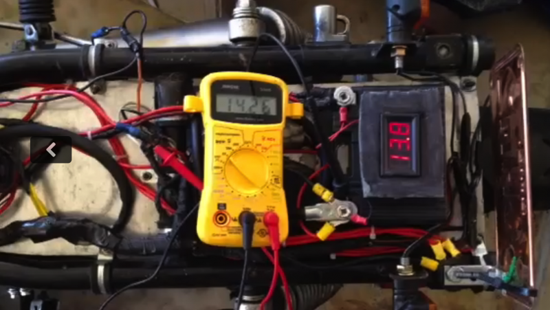
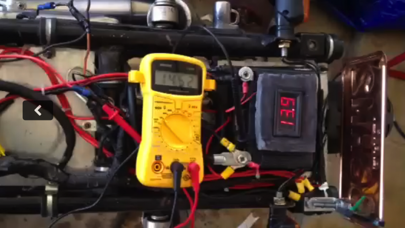
              Okay so I tested the voltage of the R/R output and the battery while the bike was off, idling, and at 5k. The left is the R/R output and the right is the battery.

              Here is a picture of it off and they are close, only .10v away from eachother:


              Here is a picture of the bike idling:


              Here is a picture of the bike running at 5K:


              Here is a video of the bike idling (a little high at 2k) and at 5k (I am really sorry the video is upside down)


              Basically at idle it seems like they are about .4-.5v away and at 5K they are about .6v away, so could the corroded wire be anywhere on my harness or is there a good starting point of where to look cause all the immediate connections of the R/R to the battery/stator are new and tight. I just got a new stator and battery and all the connections were just put on.

              Comment


                #52
                Originally posted by Legionnaire View Post
                Okay so I tested the voltage of the R/R output and the battery while the bike was off, idling, and at 5k. The left is the R/R output and the right is the battery.

                Here is a picture of it off and they are close, only .10v away from eachother:


                Basically at idle it seems like they are about .4-.5v away and at 5K they are about .6v away, so could the corroded wire be anywhere on my harness or is there a good starting point of where to look cause all the immediate connections of the R/R to the battery/stator are new and tight. I just got a new stator and battery and all the connections were just put on.
                Part of your issue is your are creating your own procedure without understanding the impact of the revised procedure


                The original and revised Phase A of the stator pages specifies that you test the drops across the positive side and the negative side separately. That will tell you if you have ground issues or issues in the positive side of your connections.


                If you have cleaned your connections and followed the recommendations of grounding then you likely don't have an issues on the ground side.

                The positive side is a little more tricky as the fuse box usually gets corroded and there is also the hidden "T" in the harness.

                See "GS CHARGING SYSTEM HEATH" in my signature for more details.

                Comment


                  #53
                  Originally posted by posplayr View Post
                  Part of your issue is your are creating your own procedure without understanding the impact of the revised procedure


                  The original and revised Phase A of the stator pages specifies that you test the drops across the positive side and the negative side separately. That will tell you if you have ground issues or issues in the positive side of your connections.


                  If you have cleaned your connections and followed the recommendations of grounding then you likely don't have an issues on the ground side.

                  The positive side is a little more tricky as the fuse box usually gets corroded and there is also the hidden "T" in the harness.

                  See "GS CHARGING SYSTEM HEATH" in my signature for more details.
                  I thought I was doing the right thing so I definitely made my own procedure out out of ignorance.

                  For some reason every response in here has been over my head, sometimes I don't get things, but once I do I feel like a dummy for not realizing what I was doing.

                  I actually just checked it again and I revved up my bike and the voltage dropped to like 6v and 8v and 10v so I feel like even more is messed up now.

                  Either way I will review your electrical thread I really never came across that till now so if I take my time with it I am sure I can make sense of things!

                  Comment

                  Working...
                  X