Announcement
Collapse
No announcement yet.
duaneage Honda R/R Question
Collapse
X
-
 Flaming Chainsaws
 -
 Legionnaire
Hey this thread is a little old but I just got my R/R from duaneage and even after reading this thread I am still a little confused.Originally posted by Flaming Chainsaws View PostThanks! I will check it out on Monday.
I have a GS450 too and was confused about the three yellow wires that go to the stator because I only have 2 and then the 3rd one is from the headlights (I think)
Basically I have a couple questions:
1) What do you do with that green/white wire that was from the headlights that plugged into the stator since now the R/R takes up the 3 stator plugs?
2) The old R/R had a red wire and a red/white wire, the red wire is hot so I plug the new red R/R wire directly into the harness, but what do I do with the red/white wire that I cut from the old R/R since the new R/R does not have one to take it's place?
Sorry about asking such crazy questions, I was just really confused even with that diagram they posted because we do not have a fuse box so it throws me off, thanks for any help you can give me!
Comment
-
the green/white wire is covered with tape; the red/white wire is covered with tape; You are bypassing the headlight loop, so these wires aren't needed, because you're wiring the stator direct to R/R. Make sure you wire R/R green direct (or almost so) to battery negative. Wire the sense wire to rear brake switch as in Duaneage's diagram. Make sure you test output- sometimes corroded wiring to brake light switch causes R/R to produce too high a voltage- anything above 15 volts is TOO high.1981 gs650L
"We are all born ignorant, but you have to work hard to stay stupid" Ben Franklin
Comment
-
 Legionnaire
Okay awesome!! So I taped off those two wires. Now it is starting to make more sense.Originally posted by tom203 View Postthe green/white wire is covered with tape; the red/white wire is covered with tape; You are bypassing the headlight loop, so these wires aren't needed, because you're wiring the stator direct to R/R. Make sure you wire R/R green direct (or almost so) to battery negative. Wire the sense wire to rear brake switch as in Duaneage's diagram. Make sure you test output- sometimes corroded wiring to brake light switch causes R/R to produce too high a voltage- anything above 15 volts is TOO high.
So I had a question about this red wire coming out of my wiring harness, it was next to the green/white and red/white wires that I taped off.
Should I connect the red of the R/R to THIS red wire or should I wire the red wire off the R/R into the red wire coming off the starter to the battery, the wire with the fuse?
In the Duaneage's wiring diagram it says connect to so it goes into the fuse box, I don't have a fuse I just have the one inline fuse.
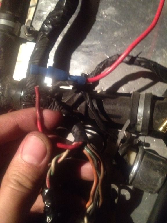
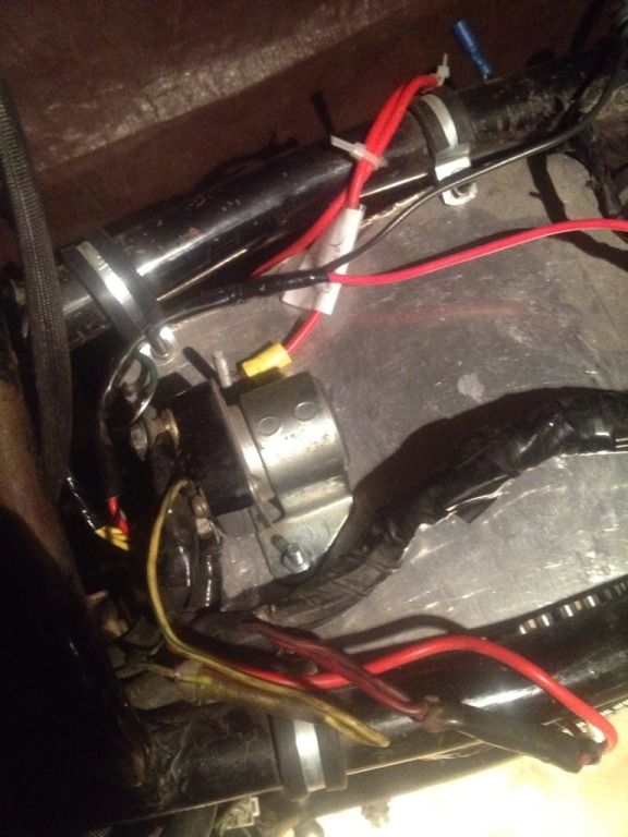
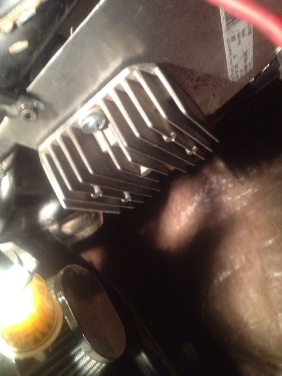
Another thing I am wondering about is grounding my R/R and starter, so I have them on top of each other on this sheet of aluminum they share the same screw. (It'll make sense when you see the photo)
I have a wire on the starter grounding it to my "star ground" the spot where all my grounds trace back to. So I think that is good, but does the R/R's actual body have to be grounded or does it ground JUST with that green wire? I am going to connect the green wire directly to my battery, but I just always thought the unit had to sit on some grounded metal as well.
Starter:
R/R: (Under the starter)
Thanks ahead of time to anyone who can take some time out of their life and give me some info, it means a lot to me!!!
Comment
-
The case of the R/R does not need to be grounded - the green wire does that ; running the green to battery and any common grounding point(s) is good. That red wire coming out of harness is where the red wire from R/R attaches to- this is positive feed into harness which powers everything when bike is running and charging system is providing power. This is how I rigged mine, but you can also run the red wire output from R/R to battery positive using a inline fuse.
Don't forget to test before you go riding off into desert- your sense wire location might need to be adjusted.1981 gs650L
"We are all born ignorant, but you have to work hard to stay stupid" Ben Franklin
Comment
-
 Legionnaire
Thank you!!!!!!Originally posted by tom203 View PostThe case of the R/R does not need to be grounded - the green wire does that ; running the green to battery and any common grounding point(s) is good. That red wire coming out of harness is where the red wire from R/R attaches to- this is positive feed into harness which powers everything when bike is running and charging system is providing power. This is how I rigged mine, but you can also run the red wire output from R/R to battery positive using a inline fuse.
Don't forget to test before you go riding off into desert- your sense wire location might need to be adjusted.
Do you have any idea where my sense wire should go that seems to be the last thing I need to know about
Comment
-
As duaneage's diagram shows, the rear brake switch is a good place; But wiring corrosion, can give a false "sense" to R/R regarding actual battery voltage. You must test it to ensure that battery voltage does not go above 15 volts (14.5 is ideal max )Originally posted by Legionnaire View PostThank you!!!!!!
Do you have any idea where my sense wire should go that seems to be the last thing I need to know about1981 gs650L
"We are all born ignorant, but you have to work hard to stay stupid" Ben Franklin
Comment
-
 Legionnaire
So I hooked it all up and it runs great and I used to drop really low with my old stator and R/R, but now It goes to like 13.6-8 when i go to 5k RPMs would the lack of voltage raise be caused by corroded wires?Originally posted by tom203 View PostAs duaneage's diagram shows, the rear brake switch is a good place; But wiring corrosion, can give a false "sense" to R/R regarding actual battery voltage. You must test it to ensure that battery voltage does not go above 15 volts (14.5 is ideal max )
Comment
-
 BassCliff
Hi,
Yes, and dirty ground connections too. Did you ground the r/r unit directly to the battery? Did you clean the main ground strap between the batter (-) and the bottom of the crankcase? Every connection should be cleaned including the fuse box, ignition switch connections, solenoid connections, blinker stalks, etc.Originally posted by Legionnaire View PostSo I hooked it all up and it runs great and I used to drop really low with my old stator and R/R, but now It goes to like 13.6-8 when i go to 5k RPMs would the lack of voltage raise be caused by corroded wires?
Thank you for your indulgence,
BassCliff
Comment
-
 Legionnaire
So I took it for a spin today and while I was stopped at a light I looked at my voltmeter and it read 14.8-15.2ish, I was just idling but I just stopped from pretty high RPMs. Is that how it should be or should it come down from 15v and go to something like 13.5v immediatly after revving it?Originally posted by BassCliff View PostHi,
Yes, and dirty ground connections too. Did you ground the r/r unit directly to the battery? Did you clean the main ground strap between the batter (-) and the bottom of the crankcase? Every connection should be cleaned including the fuse box, ignition switch connections, solenoid connections, blinker stalks, etc.
Thank you for your indulgence,
BassCliff
Thanks for the help!
Comment
-
 BassCliff
Hi,
Yes, the voltage will climb as the revs rise. Just know that corroded connections can cause the sense wire to read low and thus cause the r/r unit to push out more voltage than necessary, overcharging the battery. To check for loss, place your voltage meter between the r/r output and the battery (+) terminal. There should be less than .25v difference. The lower the better. If this voltage reading rises as the revs go up, you've still got some wiring connections to clean up.
Thank you for your indulgence,
BassCliff
Comment
-
As Basscliff said, your sense wire connection is lower than battery "sees"- best to clean up connections to keep battery happy- 15 volts is too high at idle, I bet at 4k rpm, your battery is dealing with 16 volts from the R/R.1981 gs650L
"We are all born ignorant, but you have to work hard to stay stupid" Ben Franklin
Comment
-
 Legionnaire
Okay I understand the volts go up and down according to revs, cause you had this really helpful piece on your site:Originally posted by BassCliff View PostHi,
Yes, the voltage will climb as the revs rise. Just know that corroded connections can cause the sense wire to read low and thus cause the r/r unit to push out more voltage than necessary, overcharging the battery. To check for loss, place your voltage meter between the r/r output and the battery (+) terminal. There should be less than .25v difference. The lower the better. If this voltage reading rises as the revs go up, you've still got some wiring connections to clean up.
Thank you for your indulgence,
BassCliff
Where exactly do you mean when you say the R/R output I tested here, this is the orange wire:1.) key off................Normal 12.7 volts-12.9 volts
2.) key on (but not cranking with lights for 10 sec).....Normal 12.2-12.5 volts
3.) at idle (1500 rpm).....12.6volts - 13.2volts
4.) at 2500 rpm 13.5 -14.0 volts
5.) at 5000 rpm.....14.0 -15.0 volts
6.) key off.....slightly higher than measurements # 1 (12.8-13.0 v)
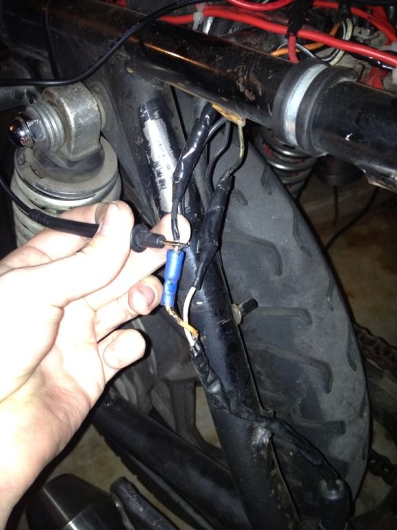
It tested like .10 away from what the battery read with the bike off and on it tested this:
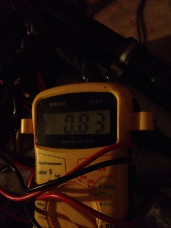
Please let me know if this is the right wire that you are speaking of and if so should I trace back this wire through the harness and inspect it or could it be a million other wires that might be corroded affecting this?
Thanks!!
Comment
-
 Legionnaire
They are bullet connections right under the tape in the picture but the rest are spade connections.Originally posted by tom203 View PostUnderneath this taping, how are these wires typically connected? You need really solid connections for charging system to work and last well.
Edit: Just wondering if I am testing the R/R output or the completely wrong wire thanks!Last edited by Guest; 04-10-2013, 02:48 PM.
Comment
.png)
Comment