.png "Powered by vBulletin")
Originally posted by 2BRacing
View Post
-
 Guest repliedI suppose I could just connect 2 wires to 87 and leave 87a unused but honestly I feel that I overpaid for the relay I got ($26.31 for the relay and the harness).
 -
Yes, the second one is correct for the coil relay mod. If you use the first relay and connect coils to 87a and 87, when the relay latches, only the coil connected to 87 will receive 12V. So either you will be running only on 1 & 4 or 2 & 3, and this can cause headaches to troubleshoot.Originally posted by Adler View PostLeave a comment:
-
Guest repliedSo I believe the relay I got is the wrong one.
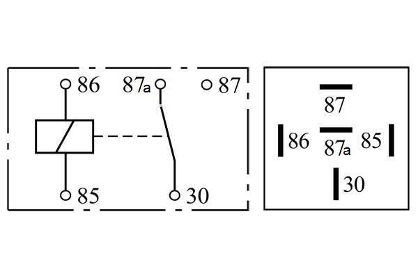
There seem to be 2 common types of bosch style, 5-pin relay.
The one I got,
and the one I should have got,
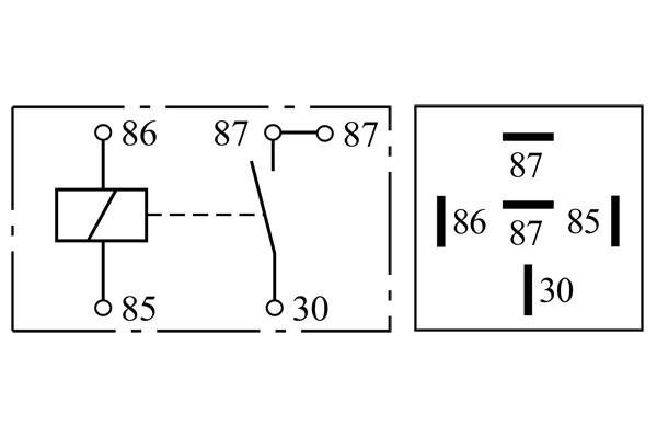
The one I got seems to switch between powering 87a and 87. the other one switches between OFF and powering both.Leave a comment:
-
Definitely heading in the right direction there! And yes, what Dueller said, best way to get that done when there's no way for them to reach unless you remove the eye terminal and properly solder on an extension.
True... it does make sense... at least my suggestion has the same result thoughOriginally posted by posplayr View Post
Just so I get this clear in my head... essentially you want everything electrical getting the correct voltage from the R/R, which becomes even more important with the Honda 6 wire setup, in that if the sense wire is sitting somewhere where it has a voltage drop, it will overcharge.
On the right track now?Leave a comment:
-
Guest repliedGood idea, I hadn't really though about how I would "splice" in the new wires.Originally posted by dueller View PostLeave a comment:
-
Guest repliedOr make up two wires with ring terminals on them. One long enough to go from the Neg bat cable point to the fuel sending unit ground and another to go from the Neg bat cable point to the frame ground. Unless this is what you meant by splicing?Originally posted by Adler View PostLeave a comment:
-
Guest repliedGlad to be of service *bows*.Originally posted by chef1366 View Post
Seems the L's are an exception to the pre-80 rule.Leave a comment:
-
Guest repliedTwo of them go directly into my "Regulator" and one goes into the harness (I hear it takes a detour to talk to my headlight?)Originally posted by chef1366 View PostLeave a comment:
-
Guest repliedI believe you may be mistaken.Originally posted by chef1366 View Post
According to the fiche the E models had separate regulators and rectifiers. The L's either didn't have rectifiers (magic!) or had them combined.
GS550E

GS550L

Leave a comment:
-
Guest repliedWell I managed to get the negative cable off the engine, so heres a small update.
The current state of the single ground.
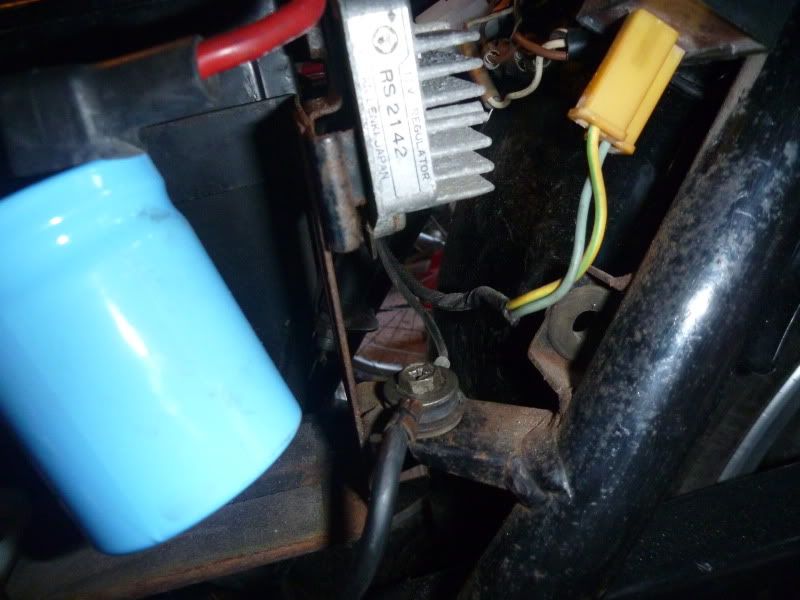
that is the R/R ground and the negative battery ground.
(Thats IS an R/R, right? I ask because it says "Regulator" on it and makes no mention of rectification)
Here are 2 stragglers who haven't found their way over to the ground point yet.
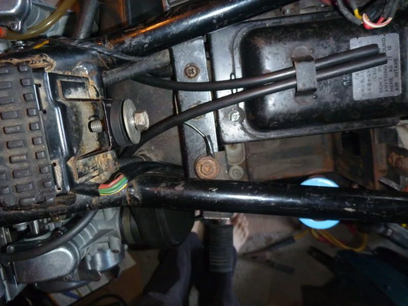
This appears to be a ground point associated with the fuel sending unit. I am guessing this isn't too important?
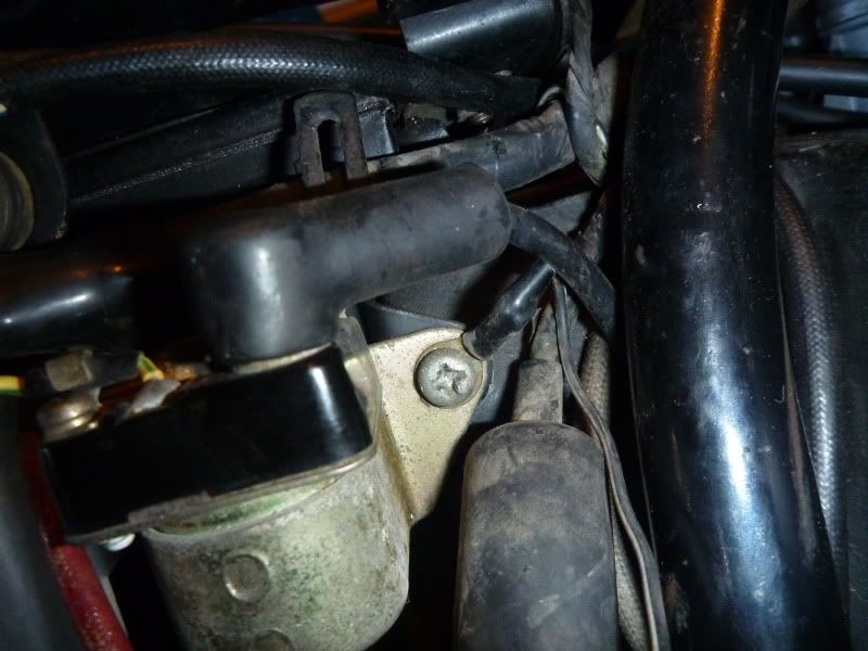
This looks like the harness ground. Unfortunately there is no way it will reach the single ground point so I may have to splice in some more wire to make it reach.Leave a comment:
-
Guest repliedI thought about making my own new negative cable and just using that but then I have a loose wire, Id rather keep it clean.Originally posted by pete View Post
Can you (or anyone) tell if the relay pictured is a normally open relay? I have very little experience reading electrical diagrams but it looks to me like the circuit is closed to 87a.Leave a comment:
Leave a comment: