Announcement

Collapse
No announcement yet.

'80 GS450 twin, electrical issues

Collapse
X
 
  • Filter
  • Time
  • Show
Clear All
new posts

    #46
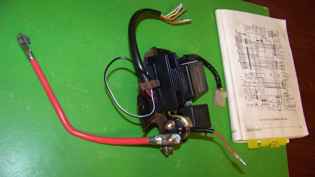
    Sooooooo...Here is the electronics plate, now featuring a new solenoid from Rick's motorsports. Turns out that the one I posted a picture of before was just a generic Ebay photo, this is what you actually get. Here I have a new positive battery lead hooked up to the lower post, when I mounted the plate onto the bike I moved it to the other, but I'm not sure where it should go.


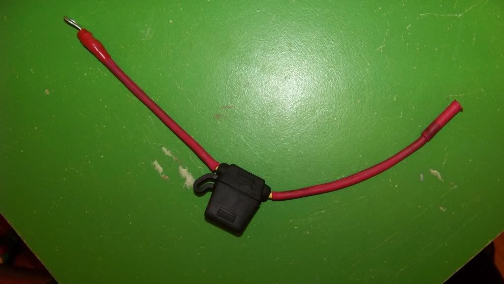
    Second photo is the inline 15 amp fuse, all ready to go...as soon as I figure out exactly where it goes...


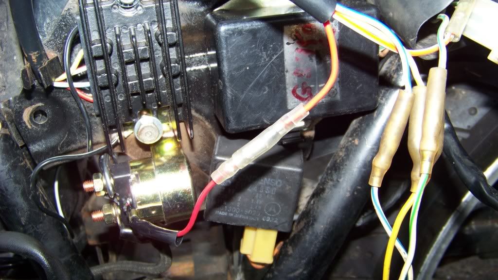
    Third pic is the components partially wired in. The three wires coming up from the bottom are off of the stator, the harness at the top of the pic is from the reg/rec. The red wire coming from there looks orange but it's a trick of the camera flash.

    Also, the negative lead coming off of the starter motor is wired to the lower terminal of the solenoid.


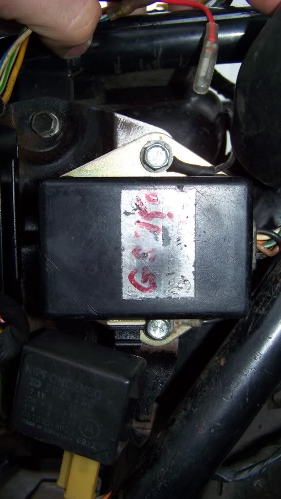
    Below is the ignitor unit, with its ground wire secured to the lower mounting bolt. I know that Pete suggested the ignitor should ground to the solenoid hardware but the lead won't reach that far...

    The ground wire under the top bolt is coming off of the main harness, the Clymer manual seemed to suggest this was correct in one of its crappy black and white photo illustrations...


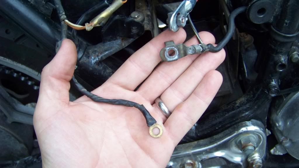
    And here is the right side of the bike. The black lead on the left is coming off of the harness, alongside of the rear brake light wires. The lead on the right looks to be grounded to the frame. Do both of these leads go to the negative battery post?

    Comment


      #47
      Looking much better! The aim with the grounds is simply to get as many as you can terminating in one common spot that also has a connection directly back to battery negative.

      The two in your second pic are definitely grounds, the one on the left relates to the rear brake light switch and the back of the harness, whereas the one on the right is really for the starter motor and coils/spark plugs to ground through which is why it's a lot thicker. Terminating on battery negative is ideal but it's also a good idea to have a ground tie between the frame and engine as well.
      1982 GS450E - The Wee Beastie
      1984 GSX750S Katana 7/11 - Kit Kat - BOTM May 2020

      sigpic

      450 Refresh thread: https://www.thegsresources.com/_foru...-GS450-Refresh

      Katana 7/11 thread: http://www.thegsresources.com/_forum...84-Katana-7-11

      Comment


        #48
        I forgot to ask, there is a black/white wire coming off off the negative lead on the left, and it's been snipped off. In the photo you can't really tell because it looks as if it's just being obscured by the positive battery terminal, but in fact it is cut off. is this the "ground tie between the engine and frame" that you are referring to Pete? As in, should I patch a wire to it with a ring terminal at the end and bolt it to the frame?

        Comment


          #49
          BTW I'll be taking OldVet66's advice (posted in another thread) and plan on picking up Stainless star washers to place on either side of each ring terminal. The more I dig through posts on the electrical subject, the more I realize just how crucial it is to have clean connections and good grounds. I've spent about as much on electrical components as I did to purchase the bike at this point -certainly don't want to fry anything.

          Oh, and I hate to push but I still need to know exactly where I am supposed to wire that 15 amp fuse into...I can't tell if it runs from the battery and plugs into the red wire coming off of the solenoid, or runs between the solenoid and the reg/rec.

          Also, how can you tell which post to bolt the pos/neg to the solenoid? They are not marked, does it matter?

          Comment


            #50
            First off, any black/white *should* be a ground wire, but check continuity with another one with the bike turned off before grounding it.

            Out of the factory, the grounds are all over the shop. Some to the frame, some to the electrics tray, one to the engine, etc. Close inspection of the wiring diagram and a process of elimination of the other grounds should hopefully help you work out what it's for.

            My suggestion earlier was based around ignoring how they were grounded from the factory and instead concentrating on as few ground connections as possible and making them all good and reliable.

            As to the fuse, the wiring diagram again should clarify that for sure, but if I remember correctly the positive lead from the battery has one large wire going to the starter solenoid, and one thinner wire going to the fuse, which then goes to power the harness from there. I think it may go into the harness near the R/R plug...

            Hang in there, you're definitely making good progress
            1982 GS450E - The Wee Beastie
            1984 GSX750S Katana 7/11 - Kit Kat - BOTM May 2020

            sigpic

            450 Refresh thread: https://www.thegsresources.com/_foru...-GS450-Refresh

            Katana 7/11 thread: http://www.thegsresources.com/_forum...84-Katana-7-11

            Comment


              #51
              Thanks, Pete. You've been EXTREMELY helpful, I really appreciate that you're taking time out to check up on my progress, especially when you've got so much time and energy going in to your own project.

              I keep studying the diagram in the Clymer, little by little it's making more sense to me but the way they have that fuse mapped out is a little sketchy -it doesn't help that there are multiple red wires that the fuse wire could conceivably link to.

              I have another version of the wiring diagram somewhere in a file, I'm going to dig that up and see if it is any clearer.

              The new handlebar controls are paid for and should ship soon, if they wire in like I think that they will then I am very, very close to completion (at least in terms of wiring).

              I'll keep at it and hopefully have some positive results soon.

              Comment


                #52
                Good stuff Trevor, and no probs at all on the helping, it's quite satisfying seeing I can be of at least some help to someone else now

                I'll see if I can get a better idea of where the fuse plugs in but not sure if I'll get in there tonight.

                I've had a couple of nights off the bike because I've been tired and feeling a touch crappy and needed to get some more sleep.

                Glad to hear you should be getting close to done too, that'll be great to see
                1982 GS450E - The Wee Beastie
                1984 GSX750S Katana 7/11 - Kit Kat - BOTM May 2020

                sigpic

                450 Refresh thread: https://www.thegsresources.com/_foru...-GS450-Refresh

                Katana 7/11 thread: http://www.thegsresources.com/_forum...84-Katana-7-11

                Comment


                  #53
                  Ok Trevor, apologies for my sieve of a memory, forgot to take pic's until tonight...

                  Firstly, remember that my electrics are not all in the stock locations and are routed quite differently, however the actual wiring in use is still the stock harness except that I simply replaced the inline fuse holder.

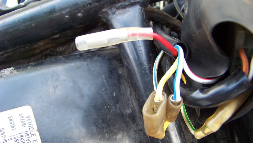
                  So, the stock fuse holder has male bullet connectors each end, so I simply put male bullet connectors on each of the my blade fuse holder like so:


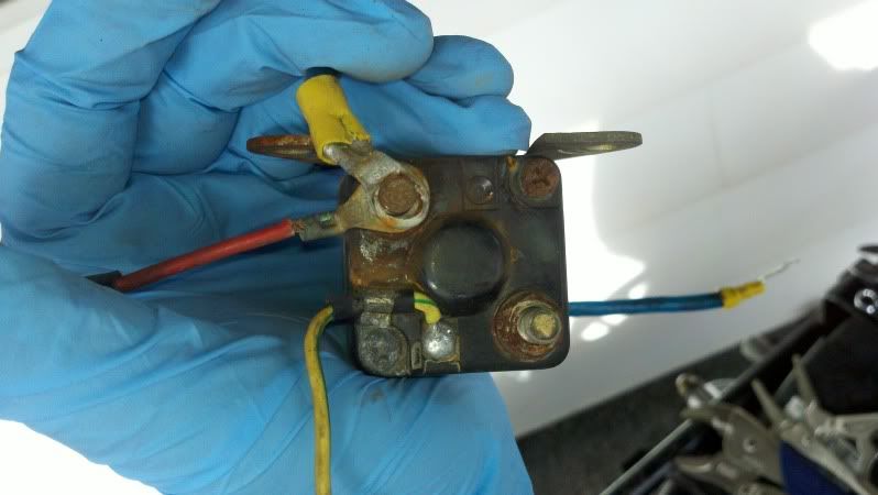
                  Now, take a look at the thick red wire that runs from one post of the starter solenoid to the positive battery terminal. As long as the PO hasn't messed with it, you should see a thinner red wire branch off from the solenoid end which ends in a female bullet connector. Note I have replaced the female bullet connector as the insulation on my stock one was had it and it was wrapped with electrical tape:


                  One side of the blade fuse's bullet connectors plugs in there.

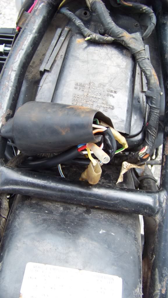
                  Next, up near the cross member of the frame when the tank mounting bolt goes through, you should see a part of the harness that has two branches coming out, one of which I think goes to the R/R plug, the other of which has a yellow/green and a red wire coming out. The yellow/green terminates in a bullet connector which plugs into the starter solenoid's yellow/green with bullet connector, and the red terminates in a female bullet connector which is for the other side of your blade fuse's bullet connector:


                  Clear as mud now?
                  1982 GS450E - The Wee Beastie
                  1984 GSX750S Katana 7/11 - Kit Kat - BOTM May 2020

                  sigpic

                  450 Refresh thread: https://www.thegsresources.com/_foru...-GS450-Refresh

                  Katana 7/11 thread: http://www.thegsresources.com/_forum...84-Katana-7-11

                  Comment


                    #54
                    Awesome, thanks Pete. I was 99% sure that was where it was supposed to go, but 1% of doubt was keeping me hung up. I made a lot of progress last night, the entire electrics plate is looking really tidy now. I may have to play around a bit more with the routing of the harness, but it's close.

                    There are very few mysteries left in terms of what goes where, there is a yellow wire coming off of the harness with a dual female plug -one yellow wire from the reg/rec obviously goes to it, where the other comes from I don't know yet.

                    I am waiting for the left and right control housings to come in, I am fully expecting them to plug in seamlessly. I'm bummed that they didn't arrive with the mail today as I have the day off and could conceivably finish the job if they were here.

                    My battery finally took a full charge, it's hard to say how many hours it took as it was removed from the battery tender a few times to protect domestic tranquility (the battery has to be charged on the kitchen counter because I have no power running to my detached garage). So anyway it is ready to go in and fire this thing up as soon as I finish patching everything in.

                    The turn signals are wired in after replacing the bullet connectors they came with with "old style" connectors that are compatible with the Suzuki connections.

                    A trip to the hardware store did not yield any "star" washers, but I did buy some stainless steel washers to uses at all grounding points. Also I wired in a ground lead with a terminal end to that length of wire coming off of negative battery cable, and grounded it to an engine bolt...pics later, but I want to make sure this is okay.

                    The last big hurdle is the harness coming off of the gauge cluster (actually there are two, I refer to the one that connects to the gear indicator) -the six-pin connector was seemingly fused together, and the wires were cut off at the main harness end. I really wanted to replace the connector and have in fact purchased one, along with all of the little gold pins, but the whole job seems a bit tricky. I may just wire it together with individual bullet connectors.

                    Comment


                      #55
                      Originally posted by Trevor76 View Post
                      There are very few mysteries left in terms of what goes where, there is a yellow wire coming off of the harness with a dual female plug -one yellow wire from the reg/rec obviously goes to it, where the other comes from I don't know yet.
                      I feel like you asked me about this already
                      Is one one those yellow wires yellow with a green stripe on it?
                      That one is the trigger wire for the solenoid for the starter (in Pete's and my pic)
                      FWIW, I'm pretty sure the red line on mine with the fuse was inline with the ignition switch and the yellow with green was what returned a signal to the solenoid to make it 'active' and start the bike.

                      Comment


                        #56
                        I this I know the connector you're talking about... double femail bullet connector.

                        I *think* the one not in use is for the run of one stator leg up to the headlight switch, but I may be wrong.

                        My R/R wiriing has been modified to remove that run so all three stator leads go straight to the R/R.

                        The 6 pin lead from the guages should be the gear position indicator harness.
                        1982 GS450E - The Wee Beastie
                        1984 GSX750S Katana 7/11 - Kit Kat - BOTM May 2020

                        sigpic

                        450 Refresh thread: https://www.thegsresources.com/_foru...-GS450-Refresh

                        Katana 7/11 thread: http://www.thegsresources.com/_forum...84-Katana-7-11

                        Comment


                          #57
                          Nope, no green stripe on the yellow wire.

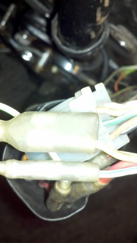
                          Here is the connection I am referring to:


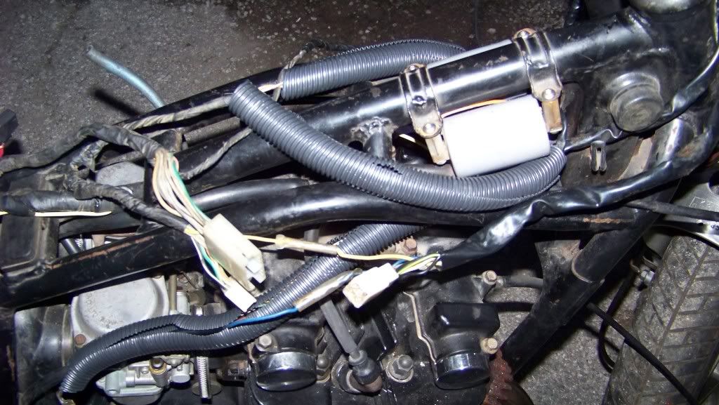
                          Here is another look at that part of the harness. In this pic you can see that the yellow/green wire that should lead to the solenoid has been snipped off at the harness. I can only speculate that there was a break in the wire, and that someone found it easier to run a new wire down the length of the harness instead of finding the break.


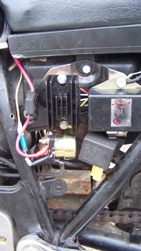
                          The electrical plate, finished. The stock setup would have a yellow wire with green tracer soldered into the solenoid, Rick's solenoid has a red wire in its place, which is in turn fed to the yellow wire that has replaced the yellow/green in the harness....got it?

                          Otherwise this setup should look pretty close to stock. The modern blade fuse holder even fits nicely where the old glass one would've gone.


                          Below is a shot of what the harness is starting to look like toward the front of the frame. This will all be taped up and zip tied into place.

                          Last edited by Guest; 09-20-2011, 11:25 PM. Reason: typo

                          Comment


                            #58
                            Oh, I forgot to mention that the rotor came in for the ignitor pick up, and it's all been fitted.

                            Comment


                              #59
                              Ah, the double bullet connector.
                              I found what you are talking about now.

                              Pretty sure we are looking at the same thing now. Definitely yellow and only one plug connected on mine.
                              Took a look and it seems to go between the stator and the R/R.
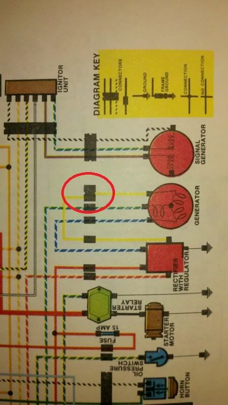
                              if you look at the diagram (mine is in color so it was easy to look at)
                              you can kind of tell that it is a double connection with only one connector on it from the diagram.

                              Comment


                                #60
                                So it's got no purpose other than to confuse me?

                                By the way apopleptic, where did you get a color diagram and what are the chances of scanning a copy of it?
                                Last edited by Guest; 09-21-2011, 12:10 AM. Reason: typo

                                Comment

                                Working...
                                X