Announcement

Collapse
No announcement yet.

'80 GS450 twin, electrical issues

Collapse
X
 
  • Filter
  • Time
  • Show
Clear All
new posts

    #31
    Well not much to update, really. I did send the Ebay signal generator back for a partial refund, and found the appropriate unit from a member here (along with the correct electrical mounting plate, and possibly an air filter holder if he can find it). Actually it all worked out pretty well as I get all of these parts for the original cost of the Ebay part...

    I am still waiting for the wiring harness and Boyer Brandsen ignition.

    In the meantime I have continued to pull the existing wiring apart and label things, but even with careful preperation I am still dreading the idea of putting it all back together. Hopefully the "new" harness will be in good shape as advertised, there's five miles of electrical tape on the current one.

    Also I took a look at the fork seals and they need replacing. As luck would have it I had a spare set for the Honda, and a quick cross reference at K&S reveals that both bikes use the same part (makes sense, they're both 33mm forks).

    When I drop the forks to do that I will be putting a set of fork gaiters on -also a cl350 leftover. As I write this I have the side covers, headlight bucket and aforementioned gaiters in the dishwasher...my wife thinks I'm doing dishes!

    Back to the electrical issue -can this bike's charging system handle a modern xenon bulb?

    And does anyone know where I can find a COLOR wiring diagram for the '80 450 E/S?

    Comment


      #32
      Maybe this has a colored wiring diagram?


      If you do buy it, please scan the colored wiring diagrams, put it into PDF file, and then send it to BassCliff.

      Comment


        #33
        Err...for twenty bucks I'd rather get this:http://www.ebay.com/itm/SUZUKI-GS400...item43a33af2a5

        Full color, inkjet printed and laminated.

        But I'd stilll rather find a link somewhere to a FREE one, I'll keep looking...
        Last edited by Guest; 09-01-2011, 10:49 PM.

        Comment


          #34
          Originally posted by Trevor76 View Post
          Err...for twenty bucks I'd rather get this:http://www.ebay.com/itm/SUZUKI-GS400...item43a33af2a5

          Full color, inkjet printed and laminated.

          But I'd stilll rather find a link somewhere to a FREE one, I'll keep looking...
          I made a color wiring diagram but I cannot find it... I just took the non-colored wiring diagram, opened it up in paint, then colored in the wires with colors. If I can find it, I'll post it.

          Comment


            #35
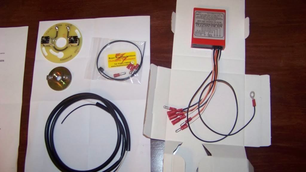
            Okay, updates: The Boyer Brandsen EI unit FINALLY came in today after a 2 1/2 week wait. It was caught up somewhere in Canada. As Pete suspected there is no accommodation for the oil pressure switch. I will get back to this later, it's going back in the box for the time being. I am going to get the bike running with stock electrics for now, I should have everything I need.


            [IMG][/IMG]

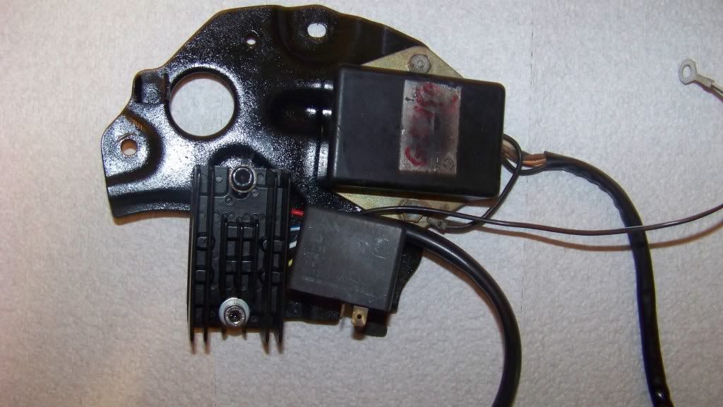
            Also since I last posted I received an electrical mounting plate as well as the correct signal generator, purchased from a member here for far cheaper than Ebay prices. (thanks, Charlie)...

            After a little love with a steel wool pad and a quick coat of rattlecan black, the mounting plate was ready to go on. Here you see that I have begun mounting the electrics to the plate. This plate looks slightly different than the one that the Schematics show for this bike -the lower left portion where the starter solenoid mounts is cut away. No matter, I'm sure I can figure out a solution.


            [IMG][/IMG]


            The wiring harness that I ordered is MUCH nicer than what was on the bike, all wires and connectors seem to be accounted for, and in good shape. I set about cleaning the bullet connectors as best as I could with a can of terminal cleaner. There is really not much dirt on them but they all seem to be off-white with oxidation, is this a big deal?

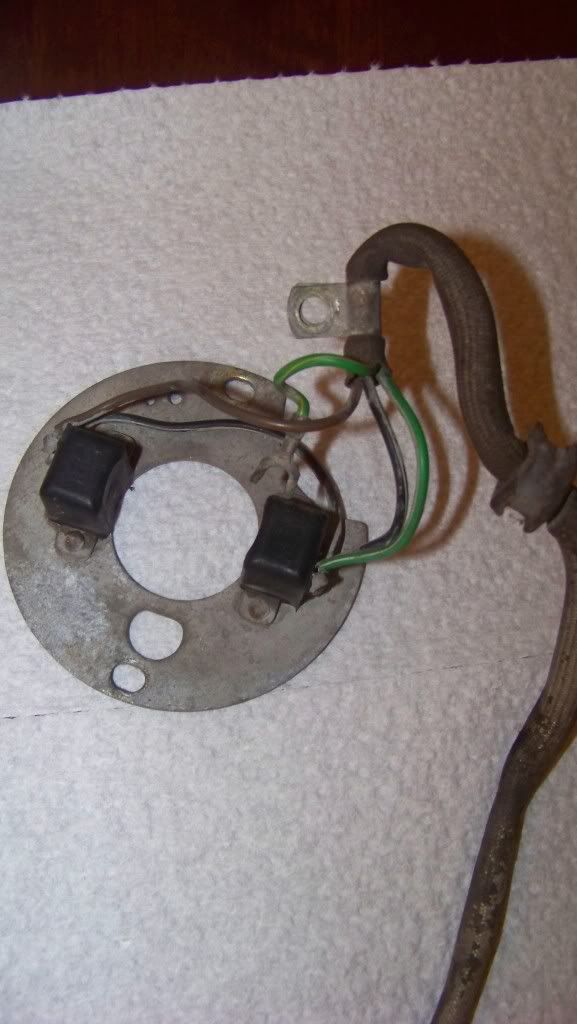
            Here are pics of the signal generator. The metal plate is also pretty oxidized and the covering over the wires is dry and brittle but otherwise seems in decent shape.

            [IMG][/IMG]

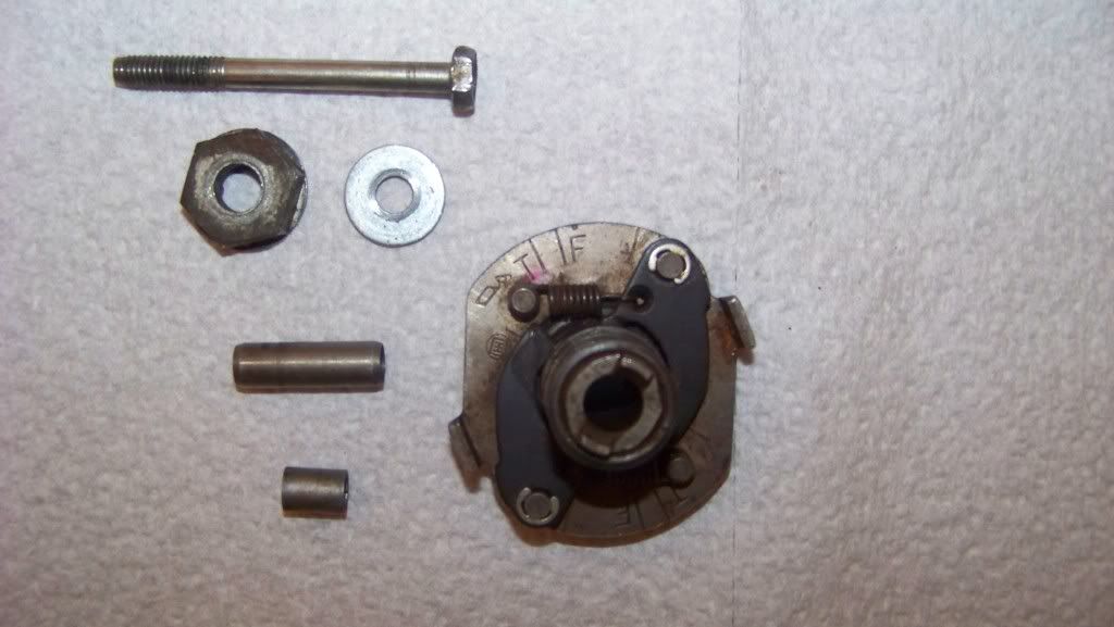
            And here is the advancer unit and related hardware. Everything is self explanatory here, except for the small spacer at the bottom.
            Where does that go?

            [IMG][/IMG]


            I will be in and out of the garage working on the bike tonight, the plan is to get the new harness in place and begin connecting all of the things that are obvious. The battery will NOT come into the equation yet, are there any other precautions that I need to take to avoid damage?

            Comment


              #36
              Originally posted by Trevor76 View Post
              Okay, updates: The Boyer Brandsen EI unit FINALLY came in today after a 2 1/2 week wait. It was caught up somewhere in Canada. As Pete suspected there is no accommodation for the oil pressure switch. I will get back to this later, it's going back in the box for the time being. I am going to get the bike running with stock electrics for now, I should have everything I need.


              [IMG][/IMG]
              Cool, looks like it should be the same deal as the Dynatek which is nearly a straight bolt in. You may or may not grind or sand an indent for the oil pressure switch screw and you will probably need about a 3mm spacer to go under the head of the hex nut on the advance plate.

              Also since I last posted I received an electrical mounting plate as well as the correct signal generator, purchased from a member here for far cheaper than Ebay prices. (thanks, Charlie)...

              After a little love with a steel wool pad and a quick coat of rattlecan black, the mounting plate was ready to go on. Here you see that I have begun mounting the electrics to the plate. This plate looks slightly different than the one that the Schematics show for this bike -the lower left portion where the starter solenoid mounts is cut away. No matter, I'm sure I can figure out a solution.


              [IMG][/IMG]
              Good stuff! One thing with that electrics tray... while it's great that you painted it (looks good too), you need to ensure any bolt point there that needs to be a ground still provides a good ground.

              The starter relay actually goes where you have the R/R (out of the factory anyway)...

              Your starter relay's mounts are the grounding points for it, and I would move everything else's grounding point there and make sure there is an extra ground wire from there directly to battery negative.

              The wiring harness that I ordered is MUCH nicer than what was on the bike, all wires and connectors seem to be accounted for, and in good shape. I set about cleaning the bullet connectors as best as I could with a can of terminal cleaner. There is really not much dirt on them but they all seem to be off-white with oxidation, is this a big deal?

              Here are pics of the signal generator. The metal plate is also pretty oxidized and the covering over the wires is dry and brittle but otherwise seems in decent shape.

              [IMG][/IMG]
              Don't worry about the oxidisation on the plate, just make sure there is 60 - 80 ohms across each pickup coil. That's black/white to brown and black/white to green/white.

              As for the connectors, a liberal spray of contact cleaner on the plug and socket then plug/unplug several times and they should be good to go.

              The only other way to improve that is to replace them...

              And here is the advancer unit and related hardware. Everything is self explanatory here, except for the small spacer at the bottom.
              Where does that go?

              [IMG][/IMG]
              Ok, so I see two items my advance unit doesn't have and I don't see one crucial item.

              The spacer I have no idea on. The long dowel type bit I don't have either, although I can see where it might need to go through the centre of the advance unit and the bolt may go through it. I don't recall mine being like that but maybe it just isn't separated on mine... if it fits it should be ok I would imagine.

              I can't make it out but there's also a thin round bit like a washer that sits on the advance plate underneath the rotor which is what allows it to rotate easily. There's a bit of a groove in the advance plate where it sits.

              The crucial bit I don't see is the rotor, on the left in the pic below (there's also a pic of the spacer you probably need with the Boyer I mentioned earlier too):


              If you have the rotor but just not pictured, then cool, and it needs to go onto the advance plate with the slots in the side over the protrustions on the weights.

              With the advance plate held so the R side is up, the twin magnets on one of the rotor protrusions (pictured) should be on the right side.

              I will be in and out of the garage working on the bike tonight, the plan is to get the new harness in place and begin connecting all of the things that are obvious. The battery will NOT come into the equation yet, are there any other precautions that I need to take to avoid damage?
              Cool, you'll be in and out during your night, I'm just having my morning coffees before heading in there today

              The only other precaution is to take your time and make sure it's connected correctly and take note of where the existing harness routes to get the new one on easier.

              Also pay special attention to all the grounds while you're at it and make sure they're perfect.

              Good luck!
              1982 GS450E - The Wee Beastie
              1984 GSX750S Katana 7/11 - Kit Kat - BOTM May 2020

              sigpic

              450 Refresh thread: https://www.thegsresources.com/_foru...-GS450-Refresh

              Katana 7/11 thread: http://www.thegsresources.com/_forum...84-Katana-7-11

              Comment


                #37
                Well, I don't have everything I need afterall. No rotor. I thought it looked a little funny when I placed the signal generator into the engine case. Nothing to spin.

                I guess it wasn't needed when the PO replaced the signal generator with points.

                I'll put a post in the wanted section and see what happens.

                Pete, thanks for the heads up about the paint on the electronics plate.
                I guess I can buff it with a dremel where the bolts contact the metal.
                And yes, the longer spacer definitly belongs on that bolt, maybe the shorter one was fitted in there to make everything fit with the points setup. I never saw where it was fitted in, it fell on the floor when I pulled the points plate out of there and I tossed it in the bag with the rest.

                Your starter relay's mounts are the grounding points for it, and I would move everything else's grounding point there and make sure there is an extra ground wire from there directly to battery negative.
                Please explain further -by "everything else" you mean the ground wire from the rec/reg, as well as the ground from the ignitor? And then one common, heavy gauge negative cable to the battery? Got a photo illustration?

                Comment


                  #38
                  Originally posted by Trevor76 View Post
                  Well, I don't have everything I need afterall. No rotor. I thought it looked a little funny when I placed the signal generator into the engine case. Nothing to spin.

                  I guess it wasn't needed when the PO replaced the signal generator with points.

                  I'll put a post in the wanted section and see what happens.

                  Pete, thanks for the heads up about the paint on the electronics plate.
                  I guess I can buff it with a dremel where the bolts contact the metal.
                  And yes, the longer spacer definitly belongs on that bolt, maybe the shorter one was fitted in there to make everything fit with the points setup. I never saw where it was fitted in, it fell on the floor when I pulled the points plate out of there and I tossed it in the bag with the rest.


                  Please explain further -by "everything else" you mean the ground wire from the rec/reg, as well as the ground from the ignitor? And then one common, heavy gauge negative cable to the battery? Got a photo illustration?
                  So is that advance plate from the points ignition? If so, then it will be 10 degrees too advanced below 1650 RPM going by what I've seen in the factory manual. I don't know if that's an issue or not, but it does at least explain the need for the spacer as the older ones with points had an 8mm bolt holding it on, whereas our 450's have a 6mm bolt.

                  As to the electrics plate, yeah just scrape some paint off around the bolt holes, no need to ruin your paint job

                  Doesn't need to be a heavy gauge wire back to the battery, just similar to what's in use for the other grounds as there shouldn't be a lot of current travelling through it.

                  I can't really show you a good photo at the moment as I haven't got a battery in mine yet and I'm not using the stock electrics plate and therefore have yet to make up my battery leads.

                  It sounds like you've got the right idea though, R/R and ignitor ground leads bolted to one of the bolts holding the starter solenoid on, and another lead made up that goes directly from that same bolt back to battery negative.
                  1982 GS450E - The Wee Beastie
                  1984 GSX750S Katana 7/11 - Kit Kat - BOTM May 2020

                  sigpic

                  450 Refresh thread: https://www.thegsresources.com/_foru...-GS450-Refresh

                  Katana 7/11 thread: http://www.thegsresources.com/_forum...84-Katana-7-11

                  Comment


                    #39
                    Okay, that does make sense and explains the spacers. So I need the entire advance unit. I think I have a lead on one, waiting to hear back.

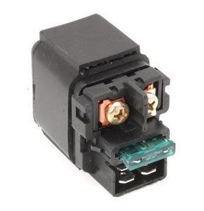
                    Regarding the starter solenoid, I found this one from Rick's Motorsports -same guys that make the reg/rec I'm using:

                    [IMG][/IMG]

                    It has a built-in blade fuse, I'm assuming that would negate the need for an inline fuse? Looks pretty trick, I'm considering buying it and replacing the solenoid sooner than later.

                    Comment


                      #40
                      Originally posted by Trevor76 View Post
                      Okay, that does make sense and explains the spacers. So I need the entire advance unit. I think I have a lead on one, waiting to hear back.

                      Regarding the starter solenoid, I found this one from Rick's Motorsports -same guys that make the reg/rec I'm using:

                      [IMG][/IMG]

                      It has a built-in blade fuse, I'm assuming that would negate the need for an inline fuse? Looks pretty trick, I'm considering buying it and replacing the solenoid sooner than later.
                      Cool, considering it was working with the points then it might be ok, but obviously not ideal, so it's probably safer to get the right one.

                      As for the solenoid, is that blade fuse complete separate to the starter circuit? The inline fuse on ours is from the battery positive to feed the main harness, and there is an additional larger gauge wire direct from battery positive to the solenoid to power the starter motor.

                      The switch for the solenoid is (from memory) a yellow/green wire with a male bullet connector which is fed from the harness via the kill switch, ignition switch, and start button.
                      1982 GS450E - The Wee Beastie
                      1984 GSX750S Katana 7/11 - Kit Kat - BOTM May 2020

                      sigpic

                      450 Refresh thread: https://www.thegsresources.com/_foru...-GS450-Refresh

                      Katana 7/11 thread: http://www.thegsresources.com/_forum...84-Katana-7-11

                      Comment


                        #41
                        I don't know, I can't find any information about this solenoid anywhere. Rick's web site doesn't have it listed with their available parts for the 450, which is strange.

                        So after tonight's session I have the harness 90% wired in, and that was done simply by matching connectors and colors. I'll use the Clymer wiring diagram to figure out the rest.
                        Only thing giving me trouble is the routing of the harness, I didn't pay enough attention to how it was routed before. I guess if everything plugs in then it's good to go, but I want to make sure that nothing is getting pinched in the moving parts of the frame, or under the seat and tank. Also don't want to fry anything by having it too close to the engine.

                        Pete do you have pics readily available of your routing? (or anyone else)

                        Comment


                          #42
                          Originally posted by Trevor76 View Post
                          I don't know, I can't find any information about this solenoid anywhere. Rick's web site doesn't have it listed with their available parts for the 450, which is strange.

                          So after tonight's session I have the harness 90% wired in, and that was done simply by matching connectors and colors. I'll use the Clymer wiring diagram to figure out the rest.
                          Only thing giving me trouble is the routing of the harness, I didn't pay enough attention to how it was routed before. I guess if everything plugs in then it's good to go, but I want to make sure that nothing is getting pinched in the moving parts of the frame, or under the seat and tank. Also don't want to fry anything by having it too close to the engine.

                          Pete do you have pics readily available of your routing? (or anyone else)
                          Bugger, just came up from the garage! I could've photo'd the routing diagrams in the factory manual for you. Charlie G did that for me before I got my factory manual, so I'll see if I can find his post somewhere.
                          1982 GS450E - The Wee Beastie
                          1984 GSX750S Katana 7/11 - Kit Kat - BOTM May 2020

                          sigpic

                          450 Refresh thread: https://www.thegsresources.com/_foru...-GS450-Refresh

                          Katana 7/11 thread: http://www.thegsresources.com/_forum...84-Katana-7-11

                          Comment


                            #43
                            Success!


                            Charlie's a legend...
                            1982 GS450E - The Wee Beastie
                            1984 GSX750S Katana 7/11 - Kit Kat - BOTM May 2020

                            sigpic

                            450 Refresh thread: https://www.thegsresources.com/_foru...-GS450-Refresh

                            Katana 7/11 thread: http://www.thegsresources.com/_forum...84-Katana-7-11

                            Comment


                              #44
                              Cool, thanks for coming through again Pete. That looks pretty close to what I've got going, I just need to wrap the harness with protective tubing and zip-tie it in place.

                              I have a few little projects to do on the bike while waiting for a timing advance unit to come along, including brake pad replacement and caliper adjustment.

                              Also I need stock control housings for the bars.

                              All in all, a very productive couple of days off.

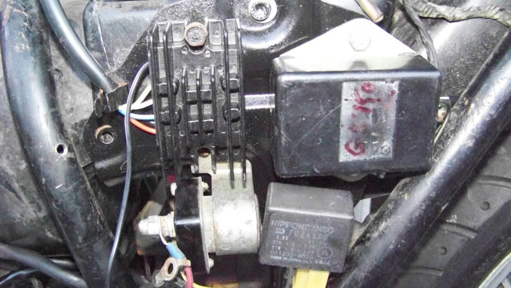
                              Here is the current state of the electrics plate.

                              [IMG][/IMG]

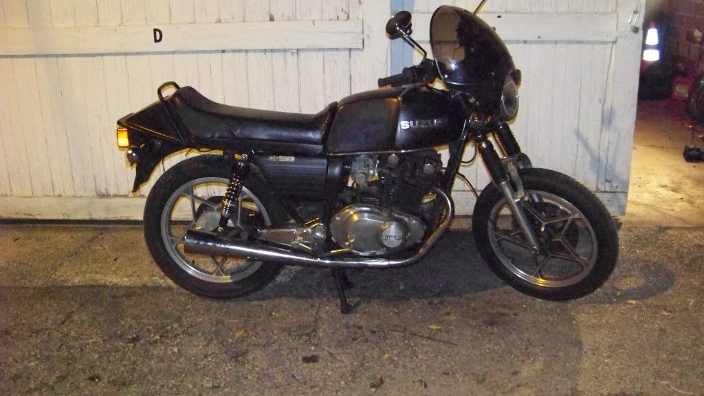
                              All put back together. (well, mocked up at least)
                              Notice the addition of fork gaiters and fork brace, Moto Guzzi fairing and new rear shocks. Also aftermarket signals.
                              [IMG][/IMG]


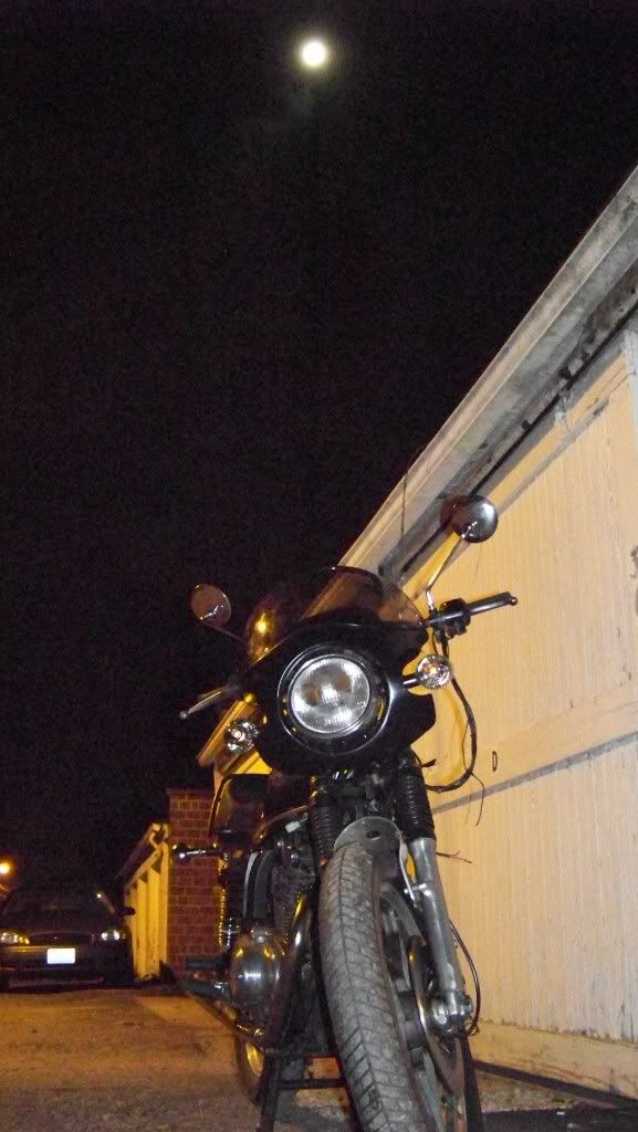
                              Spooky Suzuki!

                              [IMG][/IMG]
                              Last edited by Guest; 09-11-2011, 12:12 PM. Reason: photo swap

                              Comment


                                #45
                                No probs Trevor, and you can thank Charlie G for that one

                                Those electrics look more like I expect to see now and the bike's looking good too!

                                I ended up bending my own brace but I don't expect it will do as good a job as a real one. I may end up adding an extra layer of aluminium underneath it if it doesn't brace like I want it to.
                                1982 GS450E - The Wee Beastie
                                1984 GSX750S Katana 7/11 - Kit Kat - BOTM May 2020

                                sigpic

                                450 Refresh thread: https://www.thegsresources.com/_foru...-GS450-Refresh

                                Katana 7/11 thread: http://www.thegsresources.com/_forum...84-Katana-7-11

                                Comment

                                Working...
                                X