Announcement

Collapse
No announcement yet.

simplified wiring?

Collapse
X
 
  • Filter
  • Time
  • Show
Clear All
new posts

    simplified wiring?

    Anyone tried anything like this:


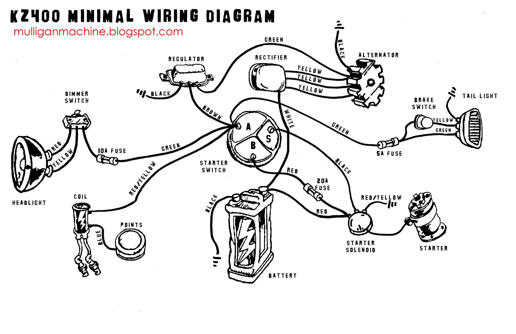
    on a GS? The more I work on my bike the more I realize there is all sorts of wiring going everywhere, very unorganized. There is absolutely tons of crap going on around the headlight since there used to be a fairing that has since been removed. What does the A, B, and S mean on the starter switch here?

    I'm thinking about redoing the entire thing, simplified, with a new wiring harness using expandable braided sleeving. Does reusing the wire inside of the harness sound like an O.K. idea?

    Here's a thread of some people that have done it before:

    I've done a simplified rewire on my XS. At some point (probably when it starts raining here in Portland) I want to do a better job running the wires. Right now I just have my wiring loom black taped together. I'd like to get things looking for like this - Anybody know where you can...


    I'm wondering what the best style of connectors will be to use, and whether to bother using multipin connectors, or just single connectors for every wire? Recommendations? Anything to watch out for?
    Last edited by Guest; 03-20-2012, 04:11 AM.

    #2
    there might be something useful here............

    Technical Info posts that are deemed to be important or popular will be placed here for easier access. If you feel a post should be moved from the Technical Info forum to here then PM the Administrator with your request.

    Comment


      #3
      Originally posted by providedrailroad View Post
      Anyone tried anything like this:
      http://i732.photobucket.com/albums/w...400-wiring.jpg on a GS?
      Yes, that question gets answered just about any time a new guy decides to take a Sawzall to the frame.


      Originally posted by providedrailroad View Post
      The more I work on my bike the more I realize there is all sorts of wiring going everywhere, very unorganized. There is absolutely tons of crap going on around the headlight since there used to be a fairing that has since been removed.
      The more you work on your bike, the less you tell us what it is. WHAT BIKE ARE WE TALKING ABOUT???


      Originally posted by providedrailroad View Post
      What does the A, B, and S mean on the starter switch here?
      Of course, it only means anything on the Kawasaki for which the diagram is made, but the A is for Auxillary, which is all the loads, B is for Battery, which supplies the power, S is for Starter. Those were determined by looking where the wires went.


      Originally posted by providedrailroad View Post
      Here's a thread of some people that have done it before:

      http://www.xs650.com/forum/showthread.php?t=12148
      Nice job, but it's on a YAMAHA. Suzukis are basically the same, but still different.


      Originally posted by providedrailroad View Post
      I'm wondering what the best style of connectors will be to use, and whether to bother using multipin connectors, or just single connectors for every wire? Recommendations? Anything to watch out for?
      Whether or not to use multi-pin connectors will depend a LOT on how many wires you end up using. If you have four wires, there is no point in gathering them all together. Stock wiring obviously has the need to keep things as compact as possible.

      .
      sigpic
      mine: 2000 Honda GoldWing GL1500SE and 1980 GS850G'K' "Junior"
      hers: 1982 GS850GL - "Angel" and 1969 Suzuki T250 Scrambler
      #1 son: 1986 Yamaha Venture Royale 1300 and 1982 GS650GL "Rat Bagger"
      #2 son: 1980 GS1000G
      Family Portrait
      Siblings and Spouses
      Mom's first ride
      Want a copy of my valve adjust spreadsheet for your 2-valve per cylinder engine? Send me an e-mail request (not a PM)
      (Click on my username in the upper-left corner for e-mail info.)

      Comment


        #4
        Originally posted by Steve View Post
        Yes, that question gets answered just about any time a new guy decides to take a Sawzall to the frame.


        The more you work on your bike, the less you tell us what it is. WHAT BIKE ARE WE TALKING ABOUT???


        Of course, it only means anything on the Kawasaki for which the diagram is made, but the A is for Auxillary, which is all the loads, B is for Battery, which supplies the power, S is for Starter. Those were determined by looking where the wires went.


        Nice job, but it's on a YAMAHA. Suzukis are basically the same, but still different.


        Whether or not to use multi-pin connectors will depend a LOT on how many wires you end up using. If you have four wires, there is no point in gathering them all together. Stock wiring obviously has the need to keep things as compact as possible.

        .
        I don't appreciate the sarcasm, no reason to be an elitist about it, and I haven't "taken a sawzall to the frame" so you can take that attitude and shove it kindly. Yes I know, it's a kawasaki diagram, and the picture is a yamaha, the electrical system is going to be more or less the same though.

        I used to do repairs and modifications to vintage recording equipment so this kind of **** is not exactly brain surgery, I'll just redraw the existing schematic and post it here when I'm finished, maybe it will help one of the guys that want to take "a sawzall to the frame" in the future. I mainly just wanted to know what people recommended as far as connectors and tubing and things go because even though the theory is the same it's still a different beast.

        It's a '78 GS750.

        Comment


          #5
          I completely rewired my bike and got rid of all of the stock wiring. The only factory wiring I have left is the wires that come from the stator to the R/R.

          Took me about 30 minutes from start to finish. If you search my posts, you'll find my diagram.

          Comment


            #6
            Cool.. Thank you, that saves me a lot of time. I think I'm still going to draw out my own and mark the color coding of the original wires, mine might be a tad different.

            Only question - the brake light switches. I see that they are in parallel so that whenever a switch is closed (front or rear), the brake light comes on. How come there is a third wire underneath that in your diagram, wouldn't that make the light "always on"?

            Comment


              #7
              Originally posted by providedrailroad View Post
              I don't appreciate the sarcasm, no reason to be an elitist about it, and I haven't "taken a sawzall to the frame" so you can take that attitude and shove it kindly.
              I never said that YOU were taking a Sawzall to it, I only said that the question is answered about as many times as someone does that.

              As far as "elitist" attitude, ... I'm proud to say that I'm as humble as they come.

              The "shoving" will be handled shortly.


              Originally posted by providedrailroad View Post
              Only question - the brake light switches. I see that they are in parallel so that whenever a switch is closed (front or rear), the brake light comes on. How come there is a third wire underneath that in your diagram, wouldn't that make the light "always on"?
              If it were connected to the brake filament, yes, it would be "always on", but there is also a tail light filament in the same bulb. That crude drawing barely shows that, and it's also incorrect in that the tail light filament should be provided power from the same fuse as the headlight, not the fuse that powers the brake light.


              "Shoving" is completed, you will see no further responses from me, on any topic, in any thread.

              .
              sigpic
              mine: 2000 Honda GoldWing GL1500SE and 1980 GS850G'K' "Junior"
              hers: 1982 GS850GL - "Angel" and 1969 Suzuki T250 Scrambler
              #1 son: 1986 Yamaha Venture Royale 1300 and 1982 GS650GL "Rat Bagger"
              #2 son: 1980 GS1000G
              Family Portrait
              Siblings and Spouses
              Mom's first ride
              Want a copy of my valve adjust spreadsheet for your 2-valve per cylinder engine? Send me an e-mail request (not a PM)
              (Click on my username in the upper-left corner for e-mail info.)

              Comment


                #8
                Originally posted by Steve View Post
                I never said that YOU were taking a Sawzall to it, I only said that the question is answered about as many times as someone does that.

                As far as "elitist" attitude, ... I'm proud to say that I'm as humble as they come.

                The "shoving" will be handled shortly.


                If it were connected to the brake filament, yes, it would be "always on", but there is also a tail light filament in the same bulb. That crude drawing barely shows that, and it's also incorrect in that the tail light filament should be provided power from the same fuse as the headlight, not the fuse that powers the brake light.


                "Shoving" is completed, you will see no further responses from me, on any topic, in any thread.

                .
                Maybe I took your response wrong, maybe you should be careful where you use caps lock, it makes you seem stand-offish. My bad.

                Comment


                  #9
                  Done a few chop wiring jobs. Here are some tips:

                  -Don't take things the wrong way, and if you do, don't go off half cocked about it. Lots people out there just trying to be helpful.

                  -Direct wire charging circuit. Good resource: http://www.triumphrat.net/speed-trip...r-upgrade.html I use those metri-pack connectors. Bought a bulk kit of 'em but mostly just use the 3 wire ones for the stator to R/R connection. Use a 30 amp inline fuse(regular blade fuse, not a mini!) Whatever connectors you use here, solder! Lots of power running through these wire, so a better connection and less opportunity for corrosion later is key. Practice on some junk crimps getting the solder to wet out well without running up the wire way past the crimp.

                  -Heat shrink! Little bits and long rolls.

                  -Use dielectric grease liberally when plugging in all your new connectors. For stock wiring, go through stock connectors cleaning and smothering in fresh dielectric grease.

                  -Don't reuse wire from the factory harness that you don't have to. Run your own new wires where you can. You be the judge on what gauge for what components. I tend to go a bit thicker for headlight and charging circuit, and all my wires are thicker than stock.

                  -Universal automotive ignition switches are nice but a bit bulky depending on how you're positioning things (stock look/airbox, fake oil bag, cafe battery hump, aka in the words of a very knowledgeable man "WHAT BIKE ARE WE TALKING ABOUT???" ) B is "battery(+)," A is "accessories," S is "start," and I is "ignition." Nice part is when you turn to start it cuts power to the A terminal(lights will turn off) giving all the power to crank things over and fire the plug.

                  -Make sure you don't cross the tail light and brake light wires. One is much brighter than the other. If you have the brake light filament as your running light, it will be nearly impossible to see the other filament come on when you hit the brakes. I only run a rear brake light switch on 2 bikes. I habitually check that it works. This allows for no wires to the bars, and only 4 to the front of the bike(1 hot for both coils, trigger wire for each coil, and the head light).

                  -Frame ground the headlight! Do not let it try to ground through the bearings. Some guys put a switch on the bucket so they can still have a high/low beam with only one (+) wire.

                  Comment


                    #10
                    The R/R can short out on the battery side and that would cause a fire in your schematic. Not the battery is not directly connected to teh R/R output in teh OEM schematics. I have a PowerPoint file with each wire that can have the color changed. PM me your e-mail if you want it. I did not look much further than that.

                    Originally posted by providedrailroad View Post
                    Cool.. Thank you, that saves me a lot of time. I think I'm still going to draw out my own and mark the color coding of the original wires, mine might be a tad different.

                    Only question - the brake light switches. I see that they are in parallel so that whenever a switch is closed (front or rear), the brake light comes on. How come there is a third wire underneath that in your diagram, wouldn't that make the light "always on"?

                    Comment


                      #11
                      Originally posted by posplayr View Post
                      The R/R can short out on the battery side and that would cause a fire in your schematic. Not the battery is not directly connected to teh R/R output in teh OEM schematics.
                      Yeah, that was the first thing a few of us mentioned in Pendulum's original thread. I like to run two regular size 30 A inline fuses. One in the R/R to battery hook up and then a main fuse from the battery(+) to the ignition switch. Then after the ignition switch either a fuse block or mini inline fuses going to the individual circuits.

                      Oil dummy light is one other thing I mentioned in Pendulum's thread. Using a lighted kill switch for that is a favorite mod of mine(details in that thread).

                      Comment


                        #12
                        Correct, my diagram did need a fuse added on the R/R output. My actual wiring on my bike is a bit different than what's shown in that diagram, but it's 95% the same. I added a fuse to the R/R and changed a few other small things as I went.

                        Comment

                        Working...
                        X