Think I understand up until the rectifier test--my diode numbers are so different from the test numbers that I am not sure I am doing it correctly.
So.. here are the numbers
1. 13.39 Ok
2. .13 Ok
3. .11-.08 (fluxuates a bit.) OK
4. between yellow wires 1.3 OK
5. between yellow wire and case- no reading OK
6. 5000rpm between yellow wires all about 73 volts OK
7. Here's where things get odd- which probably indicates a need for a rectifier
When I switch to the Diode test mode a 1 shows in the LCD.
I see no change at all when I put the red lead on the red output wire and the black lead on a yellow wire. Always shows a 1.
(Fail) Should be Pass
8. If I put the black lead on the red output wire and the red lead on the yellow wires, one at a time, I get 543, 537, 495
(Fail) Should be Pass
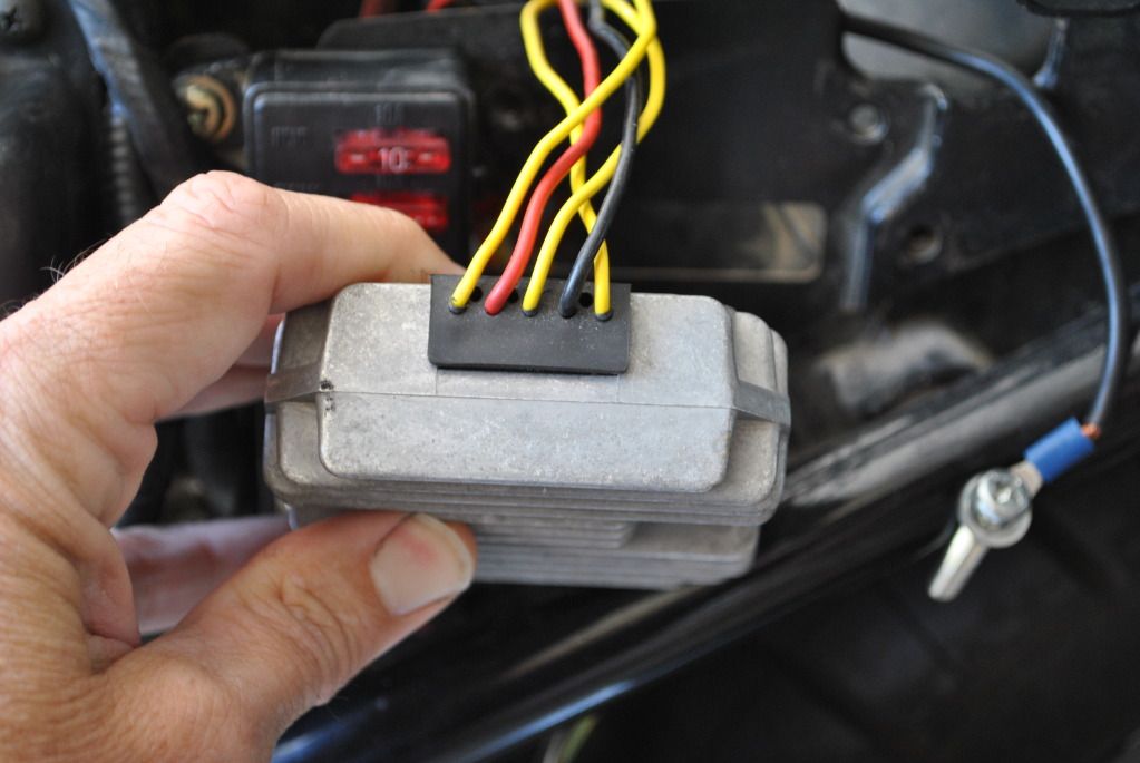
9. When I put the black lead on the black wire coming out of the regulator and the red lead on the three yellow wires--no change. The number 1 shows in the LCD
(Fail) Should be Pass
10. If I continue on the last step and attach the red lead to the black output wire and touch the red lead to the yellow leads I get a reading of 530ish for each output.
(Fail) Should be Pass
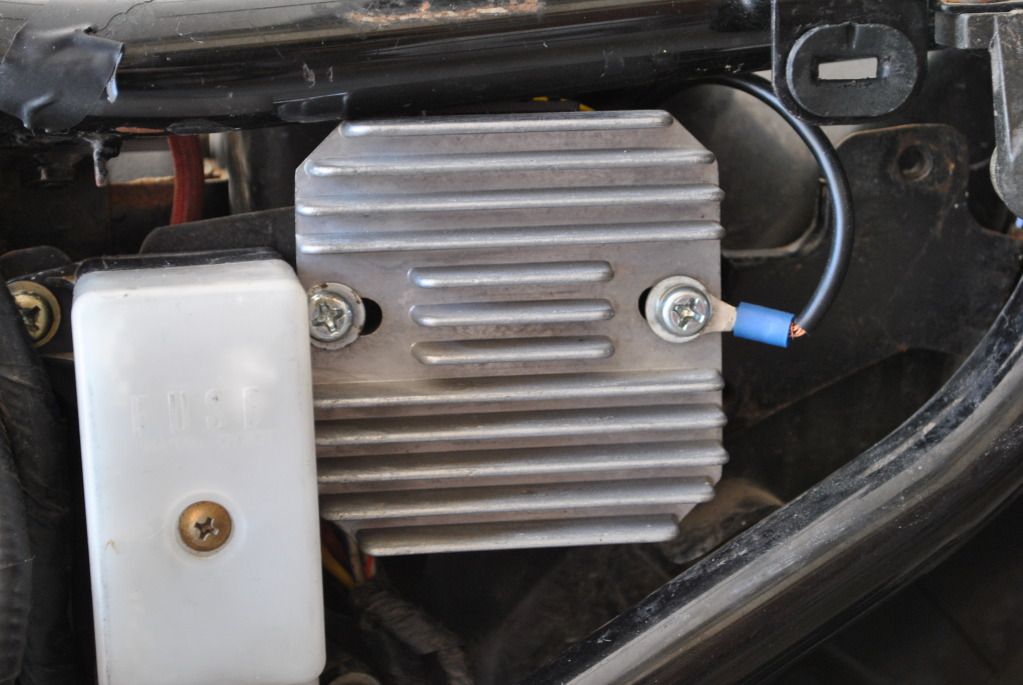
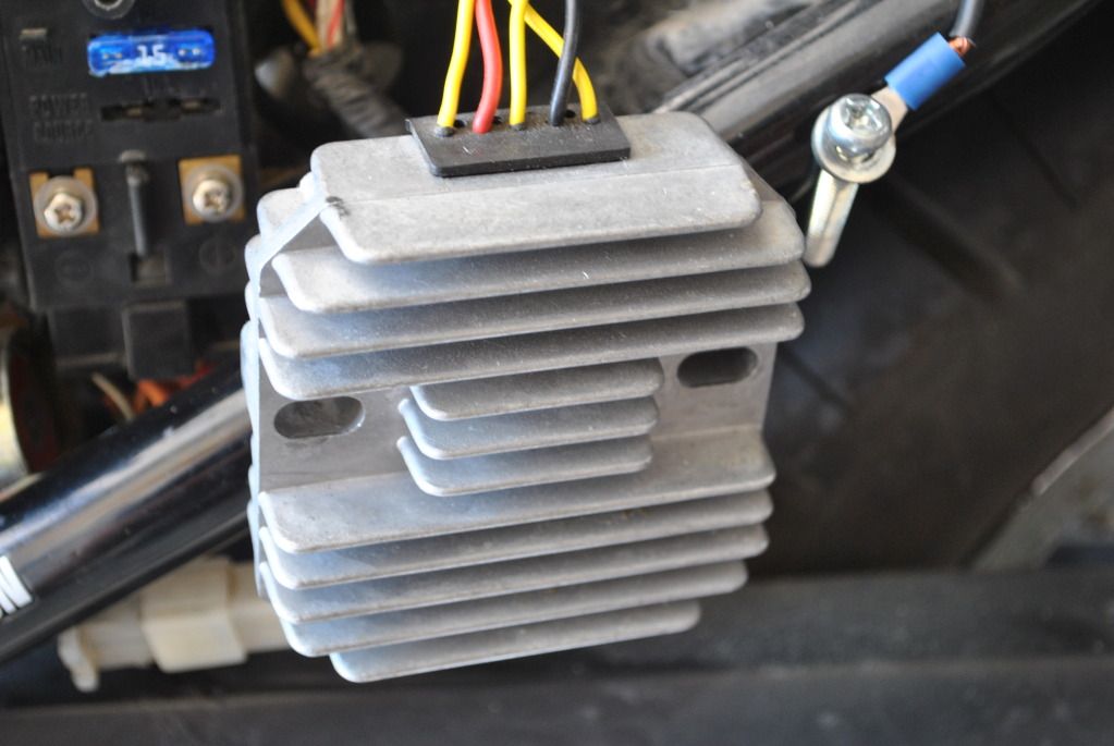
Looks like the rectifier passes. So according to Steve's post below... It could be the regulator. It could also be the battery failing to hold charge since the stator and rectifier passes the tests in the Stator Papers
Does it seem to you that I am reading the test results correctly?
.png)


Comment