Announcement

Collapse
No announcement yet.

Eastern Beaver PC-8 fuseblock wiring question

Collapse
X
 
  • Filter
  • Time
  • Show
Clear All
new posts

    Eastern Beaver PC-8 fuseblock wiring question

    So now that I'm back at it, I am working on getting the PC-8 wired up and installed on the panel. I have the PC-8 with the relay kit.

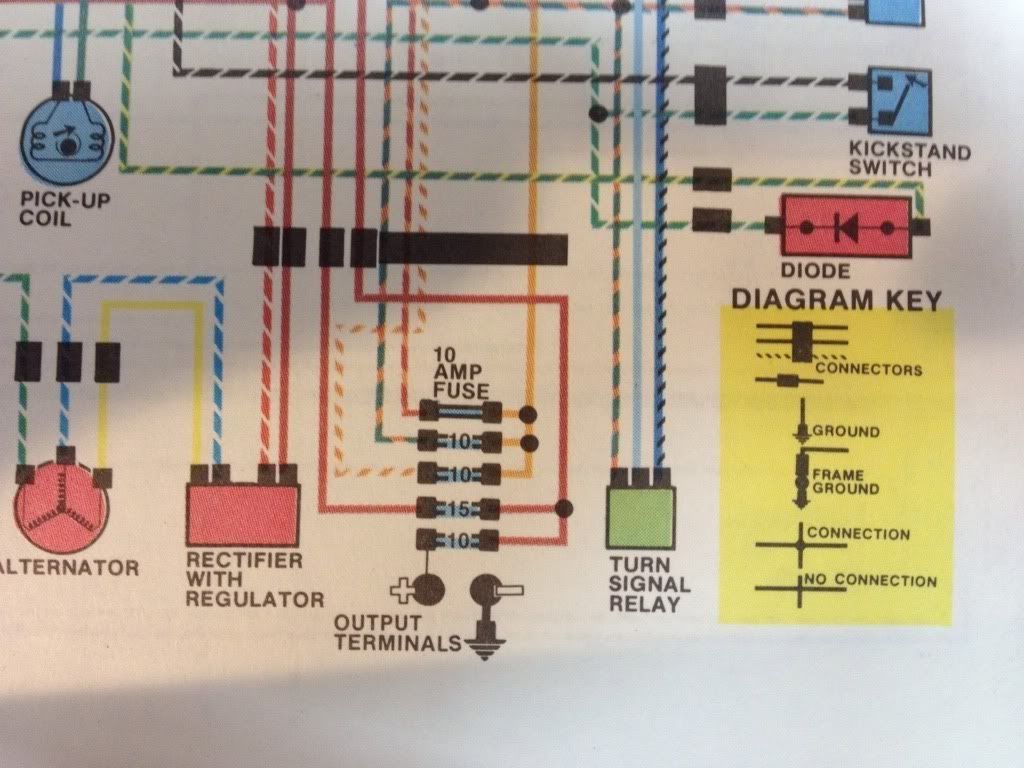
    I'm starting here:


    And need to recreate this on my PC-8:
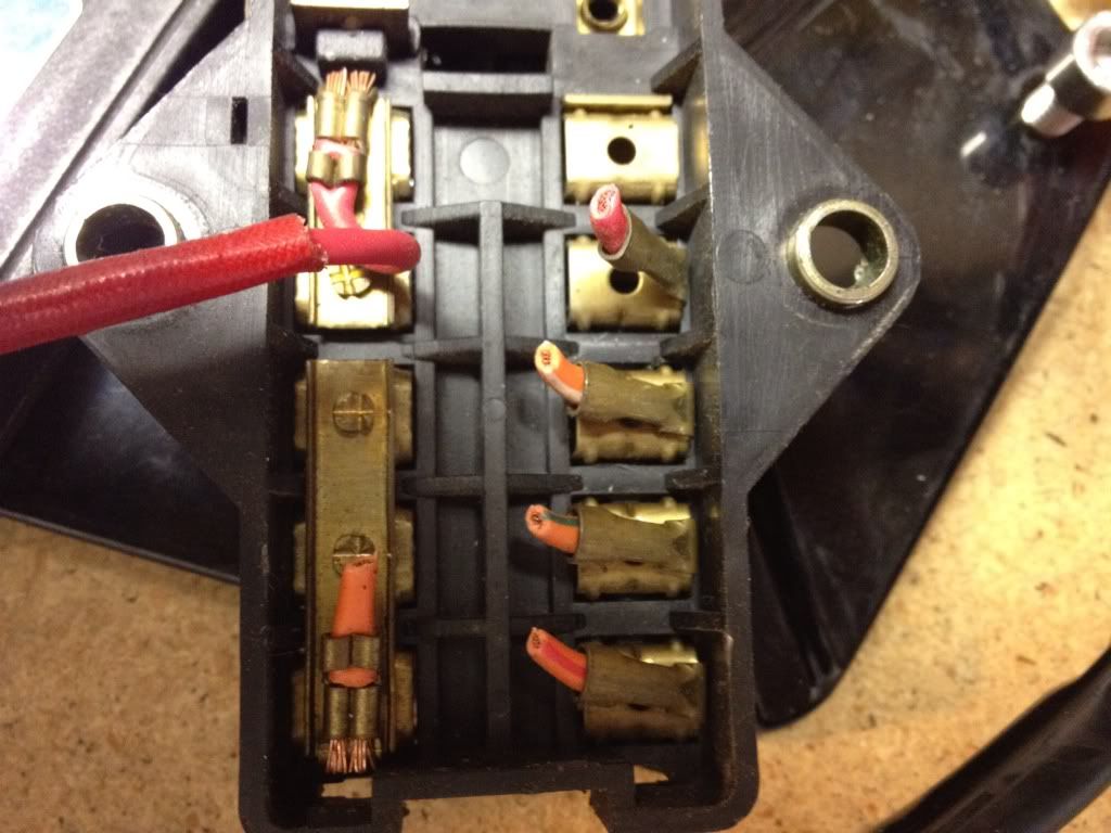


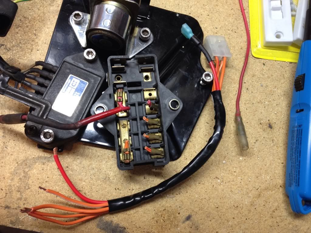
    So is this how it should be wired on the PC-8?
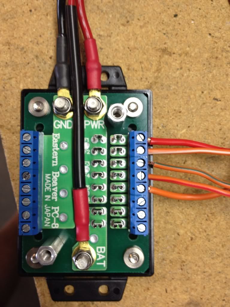

    This is just a mock up to see if the wiring is right. Not sure that it is. I'm wondering about solid orange wire.

    #2


    No difference in connections between SERIES and SHUNT R/R
    Last edited by posplayr; 06-08-2012, 12:43 PM.

    Comment


      #3
      Originally posted by Good Times View Post
      So is this how it should be wired on the PC-8?


      This is just a mock up to see if the wiring is right. Not sure that it is. I'm wondering about solid orange wire.
      Good thing you are wondering about it.

      Because it's not right.

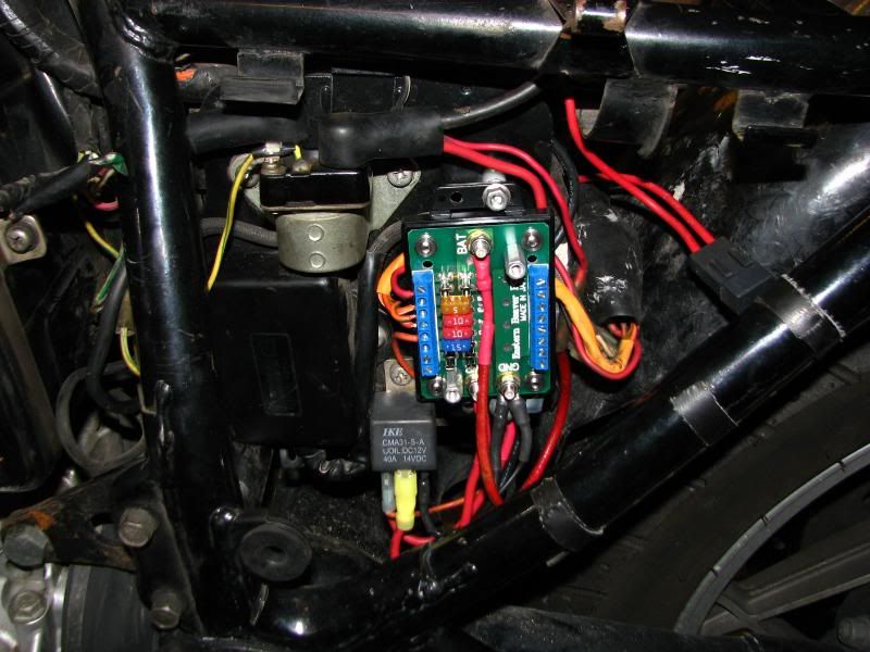
      Take a look at my Eastern Beaver install, starting with post #4.

      You really need to add a relay to this system to take full advantage of its capabilities.

      Basically, the wiring will be like this:
      - The red wire that used to feed the old fuse box can now be used to feed the EB fuse box.
      - The red wire that left the main fuse to go to the ignition switch and come back as an orange wire should be connected to one of the two fuses near the BAT terminal.
      - The orange wire that comes back from the ignition switch (the one about which you are concerned) should be used to trigger the relay.
      - The output of the relay should be used to power the PWR terminal, which feeds the group of six fuses.

      For convenience, you can somewhat replicate your stock fuse box with the EB box, as far as fuse placement is concerned. Starting with the one closest to the BAT terminal, think of that as your AUX fuse. (I use mine for connecting a battery tender when parked and plugging in electric vest while riding.) That can be a rather small fuse, depending on what you intend to connect to it. The next fuse can be thought of as your MAIN fuse, but it is really only going to power the relay, so it can be a 2 amp fuse with no problem at all. The first switched fuse would be IGNITION, followed by SIGNALS and LIGHTS. That leaves three more switched fuses for any other accessories you might want to install, like cell phone charger, GPS, etc.

      Call me if you need to, I gave you my phone number in the e-mail you sent me.

      .
      sigpic
      mine: 2000 Honda GoldWing GL1500SE and 1980 GS850G'K' "Junior"
      hers: 1982 GS850GL - "Angel" and 1969 Suzuki T250 Scrambler
      #1 son: 1986 Yamaha Venture Royale 1300 and 1982 GS650GL "Rat Bagger"
      #2 son: 1980 GS1000G
      Family Portrait
      Siblings and Spouses
      Mom's first ride
      Want a copy of my valve adjust spreadsheet for your 2-valve per cylinder engine? Send me an e-mail request (not a PM)
      (Click on my username in the upper-left corner for e-mail info.)

      Comment


        #4
        Originally posted by Steve View Post
        Good thing you are wondering about it.

        Because it's not right.

        Take a look at my Eastern Beaver install, starting with post #4.

        You really need to add a relay to this system to take full advantage of its capabilities.

        Basically, the wiring will be like this:
        - The red wire that used to feed the old fuse box can now be used to feed the EB fuse box.
        - The red wire that left the main fuse to go to the ignition switch and come back as an orange wire should be connected to one of the two fuses near the BAT terminal.
        - The orange wire that comes back from the ignition switch (the one about which you are concerned) should be used to trigger the relay.
        - The output of the relay should be used to power the PWR terminal, which feeds the group of six fuses.

        For convenience, you can somewhat replicate your stock fuse box with the EB box, as far as fuse placement is concerned. Starting with the one closest to the BAT terminal, think of that as your AUX fuse. (I use mine for connecting a battery tender when parked and plugging in electric vest while riding.) That can be a rather small fuse, depending on what you intend to connect to it. The next fuse can be thought of as your MAIN fuse, but it is really only going to power the relay, so it can be a 2 amp fuse with no problem at all. The first switched fuse would be IGNITION, followed by SIGNALS and LIGHTS. That leaves three more switched fuses for any other accessories you might want to install, like cell phone charger, GPS, etc.

        Call me if you need to, I gave you my phone number in the e-mail you sent me.

        .
        Hi Steve,

        I had asked before how people had done this. I did it a little different not using an additional external fuse holder.

        I'm assuming you have a hot wire going to the BAT terminal for growth as there is nothing connected to it (i.e. no fuse in the fuse block)

        Jim

        Comment


          #5
          Originally posted by posplayr View Post
          I'm assuming you have a hot wire going to the BAT terminal for growth as there is nothing connected to it (i.e. no fuse in the fuse block)
          The fifth picture in post #4 shows a 5 amp fuse in one of the unswitched locations. That is the one that links the "always hot" BAT terminal to the ignition switch.


          The other fuse location has been occupied since then, as the son has taken it over and added some LED accent lights (hey, he comes from a GoldWinging family ). We have installed one of the EB handlebar switches (second one down) for him to control different combinations of lights.

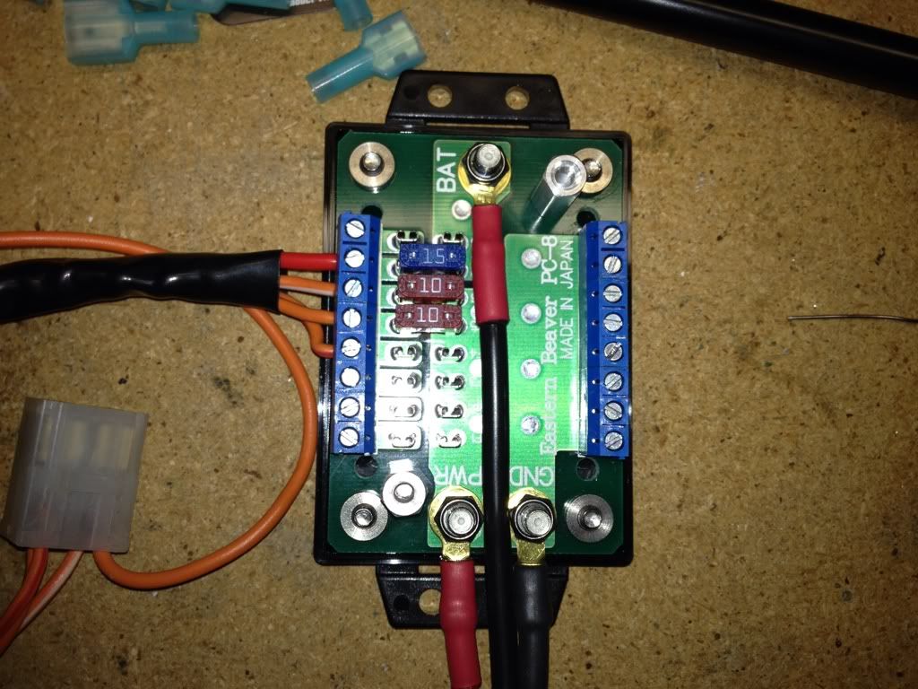
          I also installed one of these fuse boxes on my wife's 850L. ALL of the fuse positions are populated and in use.
          It was so much nicer than running a relay lead over to the terminal strip that I had installed on the other side, then branching everything off of there. Still have the terminal strip, but now it's only two rows that are powered by a fuse, instead of all of them by one relay.

          .
          sigpic
          mine: 2000 Honda GoldWing GL1500SE and 1980 GS850G'K' "Junior"
          hers: 1982 GS850GL - "Angel" and 1969 Suzuki T250 Scrambler
          #1 son: 1986 Yamaha Venture Royale 1300 and 1982 GS650GL "Rat Bagger"
          #2 son: 1980 GS1000G
          Family Portrait
          Siblings and Spouses
          Mom's first ride
          Want a copy of my valve adjust spreadsheet for your 2-valve per cylinder engine? Send me an e-mail request (not a PM)
          (Click on my username in the upper-left corner for e-mail info.)

          Comment


            #6
            After a great conversation with Steve over the phone we got it sorted out.

            Drum roll please.....

            This is the correct wiring configuration for the PC-8:


            The solid orange wire connect to the blue wire coming off the relay. I am one 10 amp fuse short.

            Thanks Steve.

            Comment


              #7
              my second diagram shows that more clearly

              Comment


                #8
                Not sure just how Good Times wired his R/R connection, but I went straight to the battery with mine. I found it easier to wire that way. Electrically, it's probably about the same, but is easier to visualize the R/R and the battery essentiall connected in parallel, then powering the bike through the new fuse box.

                .
                sigpic
                mine: 2000 Honda GoldWing GL1500SE and 1980 GS850G'K' "Junior"
                hers: 1982 GS850GL - "Angel" and 1969 Suzuki T250 Scrambler
                #1 son: 1986 Yamaha Venture Royale 1300 and 1982 GS650GL "Rat Bagger"
                #2 son: 1980 GS1000G
                Family Portrait
                Siblings and Spouses
                Mom's first ride
                Want a copy of my valve adjust spreadsheet for your 2-valve per cylinder engine? Send me an e-mail request (not a PM)
                (Click on my username in the upper-left corner for e-mail info.)

                Comment


                  #9
                  Haven't wired the R/R connection yet. That's coming after the harness is finished. I will most likely wire it to the battery.

                  Comment


                    #10
                    Thanks Posplayr and Steve.

                    Got it buttoned up this morning:


                    Comment

                    Working...
                    X