Announcement

Collapse
No announcement yet.

Digital Voltmeter install on Handlebar clamp bolts!!

Collapse
X
 
  • Filter
  • Time
  • Show
Clear All
new posts

    Digital Voltmeter install on Handlebar clamp bolts!!

    I purchased several of these units from a china based seller with good feedback.http://www.ebay.com/itm/New-4-5-30V-...item2a21cf7127
    I am impressed by the stability of the unit and the shipping was quick considering it was halfway around the globe...... Now they're selling for less than THREE BUCKS including SHIPPING.. go figure. NOW he has LCD units dayum...
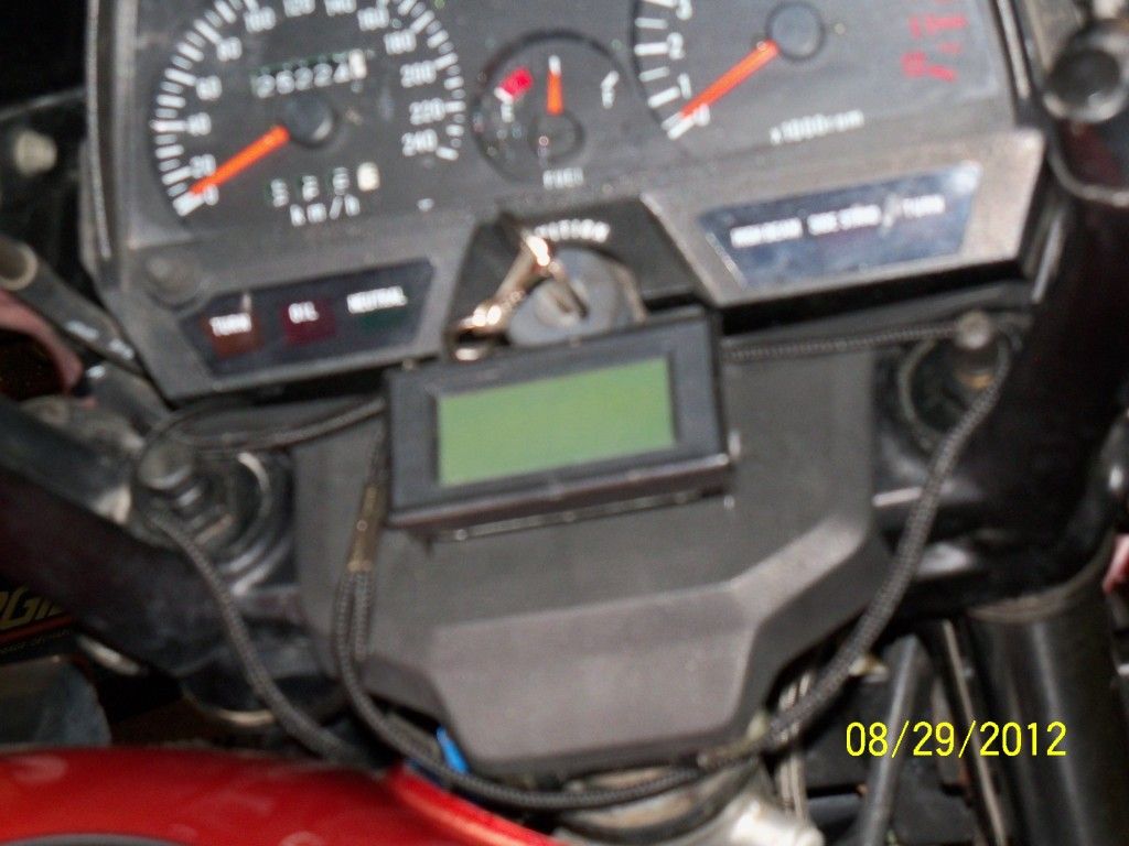
    anyway, I used a vernier caliper to measure and lay out my pattern on 1/8" stock, then cut it out with a jigsaw after drilling pilot holes for the unit itself.. it snaps into a rectangular hole. I initally had this mounted on my GS400 and it interfered with the gas door so I BENT flaps downward on the lower portion and it actually made it stronger. ALAS I'm selling the 400 so tonite I transferred it to the 450!! As you may see.. it is charging around 13.5 or thereabouts idling.. and 13.8 revved.. I hope it stays this way hahahahhah


    Last edited by Guest; 08-28-2012, 07:54 PM.

    #2
    Can't beat that price with a stick.
    http://i632.photobucket.com/albums/u...00080021-1.jpg
    1978 GS1000C
    1979 GS1000E
    1980 GS1000E
    2004 Roadstar

    Comment


      #3
      Originally posted by Rover View Post
      Can't beat that price with a stick.
      thats what I thought.. now I want the LCD unit!!!!! I'm going to see if it's backlit or not..

      Comment


        #4
        LCD unit with BLUE back light is $4.85 FREE SHIPhttp://www.ebay.com/itm/New-7-5V-20V...item231f5a5eac

        now I'm MAD but my LED unit was quoted as "waterproof". I coated the PCB with fingernail polish before mounting..just in case!!

        Last edited by Guest; 08-28-2012, 09:42 PM.

        Comment


          #5
          wiring for accurate reading.

          How do you wire these for accurate readings? Is it just a line off and pos and negative line? If it is that simple I like the extra feedback and will be ordering one as well.

          Comment


            #6
            Originally posted by gk45011 View Post
            How do you wire these for accurate readings? Is it just a line off and pos and negative line? If it is that simple I like the extra feedback and will be ordering one as well.
            I wired it to be on only with the key ON.. the red wire goes to ORANGE wire on the harness side of the ignition switch, and the black ground wire merely went to an open spot anywhere in the black/white connectors..

            I soldered and taped it onto the orange wire and used a bullet connector to the ground side.. I figured that if I placed it onto the harness side of the ignition switch, it would may indicate any problems before and including the switch, and give me an idea of voltage in the system. also that was the easiest and shortest run for the wires , which I needed to extend anyway. the stock plug supplied with the meter was only about 8 inches long. It works great.With key on engine off, if I let it sit a minute or so (headlite on) the voltage dips to under 12V. Upon starting it, it slowly climbs to around 13.8.

            Comment


              #7
              very cool. that is a nice mount, although on my 850 i ahve that rubber vainty thing plus the choke knob to contend with. might try it on the skunk though.

              Comment


                #8
                I bought a couple of these a few years ago and just put one on the 550. the problem I'm having is getting accuracy as my fuse block is not carrying full voltage and its impeded further by resistance in my kill switch. Tapping into the harness won't work.

                I'm working on installing a distribution block and will tie into that.

                I just thought I'd mention this as some newer folk may not realise that full battery voltage is not always available in the harness or at the fuse block. Another important reason to clean all connectors and insure grounds are good.

                Nice installation too. I did something similar, mounting it to a bracket that attaches to the upper tripple tree through the plastic cover:


                I'll post details on the distribution block when I get it done.
                Thanks for sharing.

                Spyug

                Comment


                  #9
                  A relay is really needed to get full voltage due to loss through the wiring harness and ignition switch.

                  Comment


                    #10
                    Originally posted by koolaid_kid View Post
                    A relay is really needed to get full voltage due to loss through the wiring harness and ignition switch.
                    He asked about that in another thread.

                    .
                    sigpic
                    mine: 2000 Honda GoldWing GL1500SE and 1980 GS850G'K' "Junior"
                    hers: 1982 GS850GL - "Angel" and 1969 Suzuki T250 Scrambler
                    #1 son: 1986 Yamaha Venture Royale 1300 and 1982 GS650GL "Rat Bagger"
                    #2 son: 1980 GS1000G
                    Family Portrait
                    Siblings and Spouses
                    Mom's first ride
                    Want a copy of my valve adjust spreadsheet for your 2-valve per cylinder engine? Send me an e-mail request (not a PM)
                    (Click on my username in the upper-left corner for e-mail info.)

                    Comment


                      #11
                      i like it.kewl.

                      Comment


                        #12
                        I like this idea as I'd recently been thinking of making some leads to more easily measure battery voltage without pulling the airbox.

                        I like the looks of the LCD voltmeter but since it is ~50% larger (dimensionally, by area it is 135% larger - over twice as big) I don't think it would fit easily on my 79, where I probably would put it directly above the handlebar between the choke knob and the ignition key (~50mm apart (1.9").
                        LCD Voltmeter 80mm x 44mm x 25mm (3.15" x 1.7 x 1)
                        LED Voltmeter 48mm x 30mm x 22mm (1.9" x 1.2 x .87)

                        Having 3mm (0.1") allowance on the top and the bottom with the LCD probably isn't enough to build a mount. The LED gives ~ 8mm (1/4"). Maybe make an hourglass shaped mount. At this price, might order both.

                        Comment


                          #13
                          I'm going to re do mine and install it in the spot where the gas guage would be. just need some time, I also thought about running a dedicated wire to the the positive side of the battery. I ordered some LCD models that will draw appreciably less current and think they could be left on continually (with a float charger in the wee months of winter )

                          Comment


                            #14
                            I just ordered 2 of the LCD ones, cheaper than dirt. I think someone should post this in the parts for sale section as this is an important add on and I came across this just by chance. Any volunteers?

                            Comment

                            Working...
                            X