Announcement

Collapse
No announcement yet.

Ignition switch how does it work?

Collapse
X
 
  • Filter
  • Time
  • Show
Clear All
new posts

    Ignition switch how does it work?

    On last weekend's Sunday run the bike (83 550E) just died on me. Back in the cave it was determined that the ignition switch was at fault. Reading up in the archives I found that a couple of guys had successfully dissassembled and cleaned them so I decided to attempt the same.

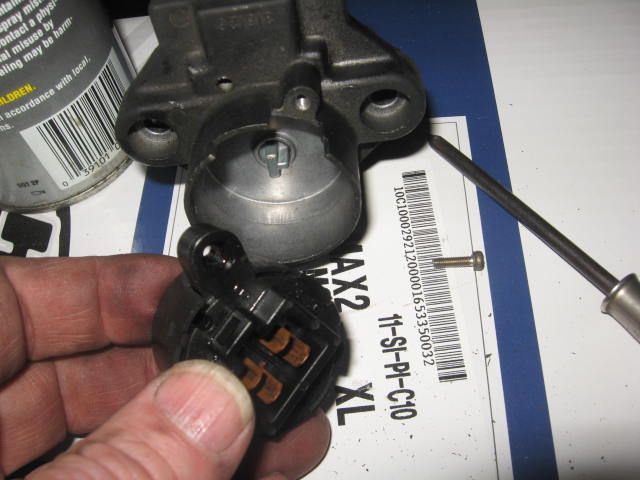
    As noted by the other members, it is a simple enough procedure. Remove the switch lock mechanism from the upper tripple tree then remove the module from the bottom of the lock (one small screw). Once the module is free, the two plastic halves can be seperated and you get this:

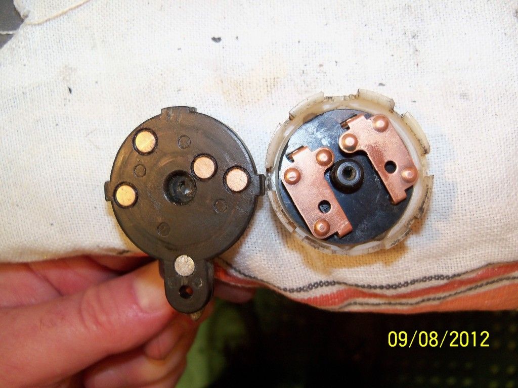
    The disk in my hand are the contacts which are connected on the other side to the wires going to the small green connector to the harness. The contacts on the left side spaced further apart are for power to the headlight and taillight. The contact toward the center is power in (red wire) the other is power out to the kill switch/start button (orange).

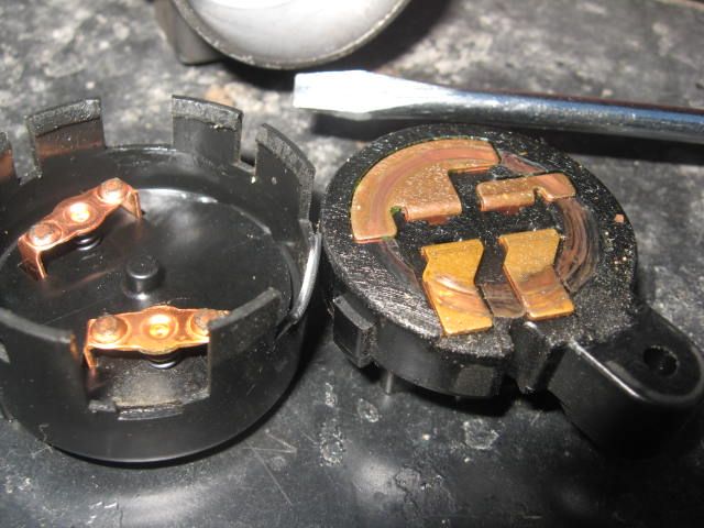
    The other disk carries the jumpers that when rotated via the lock mechanism jump the contacts to flow power back out and simultaneously send power to the head and tail lights. The jumpers are aligned in the "On" position and you can see where the bumps would touch the contacts when the halves are reassembled. But here in lies my dilemma.

    When plugged into the harness in this position, i.e. key on, I have power in and out but I do not have power to either light. I believe I can tell why. There is no method of power from the "in" contact getting to the contacts for the lights. There is just no way that I can see to arrange the jumpers to line up such that they would transfer power.

    I was very careful in dissasembly and made markings on the case to line things up and the jumpers only slot in one way to the plate that carries them. Looking at the reverse of the plate there is no connector between the jumpers and nothing fell out during dissassembly and yet at one point it all worked (and for 29 years or so).

    I've cleaned and tested the spare one I have and it is exactly same and doesn't power the lights either. I am at a loss to understand this.

    Can anyone explain this or tell me what I'm missing?

    As always all comments are appreciated.

    Cheers,
    spyug
    Last edited by Guest; 09-08-2012, 12:32 PM.

    #2
    That's normal. The oarnge wire powers the lights, too. The other side takes power from the headlight switch (grey on mine) and feeds the tail light (brown) with the ignition on. With the ignition in the parking position, it connects the red wire with the brown tail light wire.

    Comment


      #3
      With the ignition in the parking position, it connects the red wire with the brown tail light wire.
      How can that be? The jumpers don't touch those two contacts. The one jumper connects the red to the orange. The other jumper only connects the grey to the brown. As far as I can tell there is no power coming in on the grey lead. Are you saying there should be and if so what is the grey lead connected to to get power in the first place. I'm sorry, I just don't follow.

      Spyug

      Comment


        #4
        Spyug,

        I gather that you are not saying something is damaged on your switch, but more you are saying that you dont understand how it does what you think it needs to do. Lets review what it is it should be doing.

        My understanding, from looking at Suzuki factory scheamtic (1100G), is that in
        ON position it connects:
        - Red(main fuse) to the Orange (to the other 3 fuses)
        - Grn (lighting circuit) to the Brown (Tail Light).

        In Park position it connects:
        - Red (main fuse) to brown (tail Light)
        - green to nothing
        - orange to nothing

        Note: See a factory Suzuki schematic for this. Is wrong on most Clymer schematics.

        I have had mine apart. Didnt bother to figure out how that was accomplished.

        .
        Last edited by Redman; 09-08-2012, 08:09 PM.
        http://webpages.charter.net/ddvrnr/GS850_1100_Emblems.jpg
        Had 850G for 14 years. Now have GK since 2005.
        GK at IndyMotoGP Suzuki Display... ... GK on GSResources Page ... ... Euro Trash Ego Machine .. ..3 mo'cykls.... update 2 mocykl


        https://imgur.com/YTMtgq4

        Comment


          #5
          Here is picture of mine, 82 1100GK, contacts inside look different. But I image overall functionality the same.


          .
          Last edited by Redman; 09-08-2012, 08:08 PM.
          http://webpages.charter.net/ddvrnr/GS850_1100_Emblems.jpg
          Had 850G for 14 years. Now have GK since 2005.
          GK at IndyMotoGP Suzuki Display... ... GK on GSResources Page ... ... Euro Trash Ego Machine .. ..3 mo'cykls.... update 2 mocykl


          https://imgur.com/YTMtgq4

          Comment


            #6
            Well the issue I'm having is that i can't understand how the jumpers connect those contacts i.e. red to brown for instance. The jumpers just don't line up with them. If you look at the picture the jumper from the red orange side connects those two but doesn't touch or come near the grey brown contacts. I just don't see how its done.

            Thanks,
            Spyug

            Comment


              #7
              The red and brown are only connected when the switch is in the park position (with the key far right - past the on position). In that position, neither the oarnge or grey wires are connected - the only thing on is the tail light.

              I think your bike has no headlight switch, but mine connects the oarnge and grey wires when it's on, which feeds power through the ignition switch a second time then to the tail light.

              It's a complicated way of doing things to get a feature that I don't see much of a point for- the ability to have everything off but the tail light. I guess if you break down on the side of the road at night...

              I'm finding it difficult to explain, so my apologies if I'm just confusing things more.

              Comment


                #8
                Jesus Spyug that switch is incredibly clean.
                How it works don't enter into it.

                Re-assemble and move on.

                Comment


                  #9
                  Spyug, take a look at a wiring diagram you can see how the switch operates.
                  (I am referencing an 850 diagram, your bike might be slightly different.)

                  In the OFF position, nothing contacts anything else.

                  In the ON position, the red is connected to the orange, and the brown is connected to the gray.

                  In the PARK position, the red is connected to the brown.

                  In normal operation, in the ON position, power comes from the battery, through the MAIN fuse, up the red wire, through the ignition switch, back out the orange wire, then back to the fuse box to power the other three fuses. If you follow the LIGHTS fuse, you will see an orange wire with a red stripe that goes into the harness. On the way to the front of the bike, that wire goes to a connector, then continues. (That connector is the same one that has the infamous "wasted" stator loop.) On the other side of that connector, that wire changes color to yellow/white. It also branches, one side of the branch comes right back to the connector, then becomes a gray wire. That gray wire feeds the speedo/tach lights and also goes to the ignition switch. With the switch in the ON position, the gray wire is connected to the brown wire, which powers the tail light.

                  Yes, it is very convoluted, but is about the only way to put the tail light on its own circuit so that when you put the switch in the PARK position, you can power ONLY the tail light.

                  .
                  sigpic
                  mine: 2000 Honda GoldWing GL1500SE and 1980 GS850G'K' "Junior"
                  hers: 1982 GS850GL - "Angel" and 1969 Suzuki T250 Scrambler
                  #1 son: 1986 Yamaha Venture Royale 1300 and 1982 GS650GL "Rat Bagger"
                  #2 son: 1980 GS1000G
                  Family Portrait
                  Siblings and Spouses
                  Mom's first ride
                  Want a copy of my valve adjust spreadsheet for your 2-valve per cylinder engine? Send me an e-mail request (not a PM)
                  (Click on my username in the upper-left corner for e-mail info.)

                  Comment


                    #10
                    Regardless of how the switch work it likely faile ( if at all) at the connector due to a filthy connection.

                    Your fault lies not in your switch or your stars.

                    Spyug beware the folks on here who like to deviate from a root analysis by stating what may be and not what is.


                    That switch is bloody flawless.

                    Comment


                      #11
                      Thank you all. I'm still not getting any power to the lights so I'm going to have to look closer at the connectors I guess.

                      I'll let you know when I get it all working again.

                      Cheers,
                      spyug

                      Comment


                        #12
                        Originally posted by spyug View Post
                        Thank you all. I'm still not getting any power to the lights so I'm going to have to look closer at the connectors I guess.

                        I'll let you know when I get it all working again.

                        Cheers,
                        spyug
                        ah... no power to lights? You mean instrument lights? tail light? headlight?

                        You checking with a meter, or just what you can see with your eyeballs?

                        How about power to:
                        - Headlight fuse (head light)?
                        - Ignition Fuse (coils, starter solenoid)?
                        - Signal Fuse (instrument lights, tail light)? (1st, 2nd 3rd fuse in that order).

                        As multiple folks have explained above; the ignition swtich switches power to one wire (orange), and that one orange wire goes back to the fuse box and powers all three of those fuses. So if you have power on any one of those three circuits, but not the other, then the problem is not the ignition switch.

                        The other contacts on the ignition swtich effect the tail light and tail light only, just that one light.

                        [need to understand how it suppose to work, and then see how it IS working or not working, in order to determine where the problem is and isnt. Else are just randomly trying things.]

                        .
                        .
                        Last edited by Redman; 09-10-2012, 04:42 PM.
                        http://webpages.charter.net/ddvrnr/GS850_1100_Emblems.jpg
                        Had 850G for 14 years. Now have GK since 2005.
                        GK at IndyMotoGP Suzuki Display... ... GK on GSResources Page ... ... Euro Trash Ego Machine .. ..3 mo'cykls.... update 2 mocykl


                        https://imgur.com/YTMtgq4

                        Comment

                        Working...
                        X