Announcement

Collapse
No announcement yet.

R/R Replacement Project

Collapse
X
 
  • Filter
  • Time
  • Show
Clear All
new posts

    R/R Replacement Project

    Continuation of thread: http://www.thegsresources.com/_forum...d.php?t=199601

    Going to use this thread to document my R/R replacement project Hopefully it'll help me and others in the future.

    -----------------------------------------

    I have a FH014AA R/R as the replacement for what I assume is the OEM R/R. It's QUITE a bit larger than the original, and thus will not fit in the same spot.


    It looks like I can attach it to the back of the airbox though. I'm thinking I'll have to drill the holes to attach it. A couple concerns I have.
    1) The airbox is plastic. The FH014AA is supposed to be a lot cooler than the OEM R/R but it's still a concern.
    2) Attachment. Is there an adhesive that would work maybe? If I have to drill holes then I'll have to make sure to use some rubber washers to make sure the airbox is sealed properly, right?

    Here is how the R/R looks where I think it would fit. There is really no room left, it's a tight fit.


    Here is where the hook-ups would end up. I think I can route around here fine.


    Lastly, is a general R/R question. It looks like one of my stator wires ran into the wiring harness and then back out. (see screen shot below) The White/Green wire from the harness was connected to the White/Green wire from the stator. But the White/Red wire from the harness was connected to the R/R as a stator wire. I assume somewhere in the harness they connect, but I dont know how far. Can I just terminate these wires/ignore them. Or do I need to run them inline how it was previously wired?


    Also the red power line that was coming from the R/R. It's also in the harness and I'm not sure where it terminates. I'm not going to use it moving forward. I'm going to send the charge directly to the battery. Do I need to dig into the harness to properly take care of this connection?

    Thanks!

    #2
    Having just done this I know the white with red and green with white are the headlight loop.Just don't bother to hook them up.I buried mine when I wrapped them up on my 1000.Don't believe me? http://www.thegsresources.com/_forum...d.php?t=198696

    Comment


      #3
      Originally posted by SVSooke View Post
      Having just done this I know the white with red and green with white are the headlight loop.Just don't bother to hook them up.I buried mine when I wrapped them up on my 1000.Don't believe me? http://www.thegsresources.com/_forum...d.php?t=198696
      Wait...was this just a more polite way to say. "Use the search!"? heh Thanks. That helps. It doesn't necessarily hurt to USE the headlight loop, it's just more connections and thus more opportunity for connectivity issues in the future.

      Comment


        #4
        Snip off those bullets on your stator wires and install spade terminals. Then connect the spades directly to the R/R. Bypass the hand control loop for sure as it performs no function other than adding resistance.

        Your R/R ground can go to the frame or battery. Just don't send it to the battery box or that electrical side plate unless you add another subsequent ground wire going to the frame. The R/R output can go to that red wire with the bullet, but you must check resistance going to the battery. Look for Jim Posplayr's updated Stator Paper's check to do the job right. On my bike that circuit was creating about 1/2 volt drop so I had to clean all the terminals after removing them from the plastic harness shells. Not a hard job at all, you just need to get over the mental inertia of doing that kind of work.

        Good luck
        Ed

        To measure is to know.

        Mikuni O-ring Kits For Sale...https://www.thegsresources.com/_foru...ts#post1703182

        Top Newbie Mistakes thread...http://www.thegsresources.com/_forum...d.php?t=171846

        Carb rebuild tutorial...https://gsarchive.bwringer.com/mtsac...d_Tutorial.pdf

        KZ750E Rebuild Thread...http://www.thegsresources.com/_forum...0-Resurrection

        Comment


          #5
          Originally posted by MAJikMARCer View Post
          Wait...was this just a more polite way to say. "Use the search!"? heh Thanks. That helps. It doesn't necessarily hurt to USE the headlight loop, it's just more connections and thus more opportunity for connectivity issues in the future.
          No that was not my intent.But yeah I asked the same question not long ago.

          Comment


            #6
            Any thoughts on the placement of the R/R?

            Comment


              #7
              Originally posted by MAJikMARCer View Post
              Any thoughts on the placement of the R/R?
              How about on underside of seat?
              1981 gs650L

              "We are all born ignorant, but you have to work hard to stay stupid" Ben Franklin

              Comment


                #8
                Originally posted by tom203 View Post
                How about on underside of seat?
                Not much room there. Plenty of room in the tail. Any issues with wire length?

                Comment


                  #9
                  Plenty of room in the tail. Any issues with wire length?
                  (Re: moving the R/R to the tail since there isnt room next to the battery any more)

                  Anyone? Guys? Bueller?

                  I know a lot of the cafe guys move their electrics around, into the tail. I'm just worried about resistance/heat. Should I go with larger gauge wire or are the lengths we are talking about still short enough that it's not a problem?

                  Comment


                    #10
                    Please compare the distances and repost both. I can look it up for you.

                    Comment


                      #11
                      Originally posted by koolaid_kid View Post
                      Please compare the distances and repost both. I can look it up for you.
                      The original R/R had only about 10 inches of wire, before it tied into the wiring harness.

                      If I move the R/R to the tail of the bike, I'm looking at between 24-30 inches, maybe up to 36 inches depending on routing.

                      It looks like the original wires were 16 gauge. The red 'hot' wire looks like it was 14 gauge.

                      Comment


                        #12
                        The red one is the one you care about. Let me look it up for you, I'll report back. I'll do worst case of 36".
                        You will be fine with 14 gauge.
                        Last edited by Guest; 09-17-2012, 10:36 AM.

                        Comment


                          #13
                          OK FINALLY I got everything together! I had ordered parts from Eastern Beaver and didn't realize I was ordering from Japan, so the order took longer than I expected. Very happy with the parts though.

                          To recap:
                          My charging system died. After some GSR crash course electrical I was able to determine that the R/R had died. Thanks to old_skool for helping me find a replacement R/R. I ordered a FH014AA on Ebay.

                          Of course as nice as that R/R is it has some challenges of it's own. Namely that the connectors are Honda specific and not readily available online and I was unwilling to hunt down a used connector or call Honda and order what I'm sure would have been a very pricey part. Next problem. The male spade connectors are NOT the standard 1/4 inch connectors you are most likely to find at your local store. These are .312 inch connectors. Anything else will not work right. The only place I was able to find these was Eastern Beaver.

                          The other issue with the FH014AA on my 650E is that it's a LOT bigger than the OEM R/R, so I had to relocate it. There were a few options near the battery/air boxes but nothing I felt comfortable with. So I elected to place it under the rear cowl, just in front of the brake light. I'm still not super happy with that location, but it does work.

                          So finally this weekend I was able to start the build. All connections are soldered and shrink-tubed. The shrink-tube from Eastern Beaver has heat activated glue also, so these things are set once completed. My only regret was having a cheap crimper. The connectors from Eastern Beaver are the non-insulated kind, so finding a crimper that could crimp them was tricky at my budget. I didn't want to spend $60/70 on a crimper for this job, though I'm sure it would have been much better.

                          With the shrink tube, you'd never know how ugly the crimps are underneath.


                          Here is the location of the R/R now. The original plan was to silicone or resin the connectors in place, but I think I'm going to hold off until I'm certain that is the final location of the R/R. The connectors are all very firm and the shrink tube in insulating the connectors from one another very well.


                          The 'hot' wire was done in 12 gauge wire with a 30amp inline fuse:


                          Not pictured, the ground wire. I did a 14 gauge wire to the battery ground post, as well as a smaller 18 gauge wire, both crimped together to the R/R post, attached to the frame. Just a little extra insurance.

                          The stator wires were done in 16 gauge yellow wire. Rather than individual connectors for the connection to the stator I used a three-gang connector. I thought, why not? they'll always be connected at the same time and it simplifies things if I need to move stuff around.


                          And connected up on the bike:


                          I connected up the line-line fuse where the old R/R used to connect:


                          Lastly, just for reference, in case anyone else buys the FH014AA:


                          In the end the bike is charging up great now. I haven't yet taken her for a test ride, but preliminary tests with the voltmeter are very positive (get it? )
                          Last edited by Guest; 10-01-2012, 02:08 PM.

                          Comment


                            #14
                            Very clean install. Nice work!

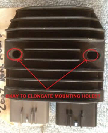
                            I have a question: does anyone know if i can egg-out the mounting holes on this Rubicon R/R without harming unit's internals?? Need another .125" to clear fuse box. Thanks, and sorry about the thread jack, Marc.

                            '80 GS1000ST
                            '92 ZX-11
                            Past rides: '79 GS1000SN, '84 GPZ900R

                            http://totalrider.com/

                            Comment


                              #15
                              I just grabbed an FH014AA from a 2008 CBR. Which connectors did you end up with from Eastern Beaver? I looked through that site and he sells some .250" kits, but doesn't list the ones for the FH014. Indeed, he says

                              FH014 as found on newer CBR1000RRs has a totally different pair of connectors. I'm sorry I can't help you with these types. I suggest NOT buying that type for an upgrade.
                              So where can I get some pigtails or female terminal connectors that will fit the inbound R/R?

                              Comment

                              Working...
                              X