So I found this link that talks about connecting up to the primary coil circuit, and I looked at the Megasquirt link posted. I'm starting to understand the use of an opto-coupler (no need to worry about voltage swings affecting the MCU), but what's odd to me is that instead of using (+) Vcc to power the opto-coupler allowing the TCI to be the ground switch, they are sourcing (+) from the coil when the TCI switch is open (firing the coil). Maybe they needed it to be reversed (input pin LOW when TCI switch is open)? It just seems odd to even involve the coil as that's one more part you need to factor into the equation. There's a very good chance I've interpreted it all wrong though
Announcement
Collapse
No announcement yet.
Arduino Tachometer - How to interface w/ ignitor?
Collapse
X
-
Originally posted by powderhound View Post
So I found this link that talks about connecting up to the primary coil circuit, and I looked at the Megasquirt link posted. I'm starting to understand the use of an opto-coupler (no need to worry about voltage swings affecting the MCU), but what's odd to me is that instead of using (+) Vcc to power the opto-coupler allowing the TCI to be the ground switch, they are sourcing (+) from the coil when the TCI switch is open (firing the coil). Maybe they needed it to be reversed (input pin LOW when TCI switch is open)? It just seems odd to even involve the coil as that's one more part you need to factor into the equation. There's a very good chance I've interpreted it all wrong though1983 GS650G
Build thread: http://www.dotheton.com/forum/index.php?topic=66251.0
-
powderhound
I will absolutely post the results that I get!
Originally posted by JonnyC View PostUgh, I've been looking at that and other links for a while now, but I still don't get it. For some reason it is very difficult for me to think conceptually when it comes to electricity.
Assume that Figure 2 from the link is using two Zeners each with a 10V breakdown voltage.
If the output voltage is between -10V and 10V, then no current will flow to GND because the Zeners act like normal diodes. As soon as the output tries to go above 10V, ZD1 starts to conduct (ZD2 also conducts in that direction), so current flows to GND until the voltage on the output goes down to 10V. In reverse, when the voltage tries to go below -10V, ZD2 starts to conduct (ZD1 already conducts in that direction), and the voltage is limited to -10V.
This effectively limits the output to +/- 10V.
The alternative is to use a single Zener like this:
This should limit the output to -0.65V - 12V (for a zener with a 12V breakdown).
I'm really looking forward to seeing what the COIL- voltages look like to see if they're a good candidate for connection to a micro.
EDIT: I also found this, which gave a great description of the tach inner workings.
Comment
-
Thanks (better late than never) for the explanation powderhound. I did more reading on Zener diodes and diodes in general, and I'm understanding them now. At first I didn't understand how the last example allowed negative voltage output, but realized the diode has a forward voltage of about .7v.
I just ordered an ARM DSO Nano for ~$65, so I will be able to inspect the primary coil when I get my bike up and running.
I got my Arduino and display unit, and have a basic RPM calculator using an external switch on an interrupt to simulate the primary coil circuit. Not working so hot because the signal is so crappy (major switch bounce), but I'm not going to bother doing any type of RC filtering if the primary coil signal is close to a square wave. Although it might not hurt either so that it's more universal. I'll be excited to use the signal generator of the DSO to simulate the primary coil circuit.1983 GS650G
Build thread: http://www.dotheton.com/forum/index.php?topic=66251.0
Comment
-
Well I got my DSO Nano and used the signal generator to test the tachometer. Working well so far, although I need to build in some smoothing. I might have to truncate the output resolution down to 3 or 4 digits, as when you're in the 10k RPM range there's no need to know the exact RPM.
I'll be excited to measure the coil signal with the DSO, but I still have a lot of work to do before I get the bike wired up and running.1983 GS650G
Build thread: http://www.dotheton.com/forum/index.php?topic=66251.0
Comment
-
powderhound
What signal are you using right now? I'd love to see how you've wired everything up.
It sounds like you've made a ton of progress. Unfortunately, it's going to be a while before I can get our scope hooked up to the bike as I just ripped out the carbs and airbox for a rebuild and then got slammed at work.
Comment
-
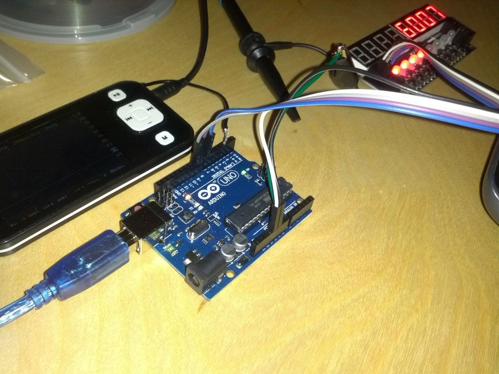
I'll take a picture tonight. It's exactly like this though - http://www.youtube.com/watch?v=9tiH5DL0Xdc. He just has the newer DSO Nano. The ground from the DSO is connected to the Arduino ground, then the signal generator output is hooked up to one of the input pins that is set as an interrupt. The output of the DSO when running on battery is 3.7 v, so it's below the 5v of the Arduino.
I hope to write a program just like his, where min RPM and max RPM can be set.
Once I get the program working, I can see what is needed to get it to work on the bike. Then I have to start thinking about the housing, which is a whole other hurdle.1983 GS650G
Build thread: http://www.dotheton.com/forum/index.php?topic=66251.0
Comment
-
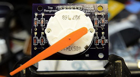
Saw this today and thought of this thread:
Throw some blinking LEDs on a project and it’s bound to make the front page of Hackaday. We do love builds of a more analog character, though, and this analog gauge stepper motor breakout boa…
Apparently the stepper motors they use in car dashes are quite cheap to acquire. I'm probably going to need a new clocks and wasn't looking forward to buying them, so maybe I'll build new ones instead! (My speedo squeals like a stuck pig and the cable connector on the tach is broken.)
Comment
-
It's really amazing what you can do with these Arduinos.
Here are some pictures I snapped of my setup so far...
Last edited by JonnyC; 01-25-2013, 05:26 PM.1983 GS650G
Build thread: http://www.dotheton.com/forum/index.php?topic=66251.0
Comment
-
Now I'm considering utilizing an Acewell mechanical to electrical speed sensor cable to include a speedometer on this. I'm not sure if they have one that fits the GS, or how it actually works (hall sensor? seems as though there is only one wire coming from the sensor). But if I do that, I really should use an OLED display to make it more robust and allow for an odometer and such. And if I do that, I should really create my own circuit board to mount all of these components in a specific housing.
Maybe I should just hook it up to my bike to see if it works first1983 GS650G
Build thread: http://www.dotheton.com/forum/index.php?topic=66251.0
Comment
-
powderhound
Yay feature creep
If you do end up going down that route, BatchPCB.com has a really great (cheap) PCB manufacturing service if you don't want to deal with etching yourself.
I wish I could get home to work on my bike! Though being stuck at work playing with 3d printers isn't horrible.
Comment
-
Originally posted by powderhound View PostThough being stuck at work playing with 3d printers isn't horrible.1983 GS650G
Build thread: http://www.dotheton.com/forum/index.php?topic=66251.0
Comment
-
Originally posted by powderhound View PostYay feature creep
If you do end up going down that route, BatchPCB.com has a really great (cheap) PCB manufacturing service if you don't want to deal with etching yourself.
I wish I could get home to work on my bike! Though being stuck at work playing with 3d printers isn't horrible.Dogma
--
O LORD, be gracious to me; heal me, for I have sinned against you! - David
Skeptical scrutiny is the means, in both science and religion, by which deep insights can be winnowed from deep nonsense. - Carl Sagan
--
'80 GS850 GLT
'80 GS1000 GT
'01 ZRX1200R
How to get a "What's New" feed without the Vortex, and without permanently quitting the Vortex
Comment
-
powderhound
We're currently working with the Replicator 2 from Makerbot. We're just getting started working with it, but if you have CAD files (STL specifically) I would be happy to try out a test print.
My co-worker and I have long-term plans to build a full dash for our bikes (he has an 82 Honda Nighthawk) as we're both planning on doing builds. They'll probably be a long time coming as we're swamped at work, but it's a fun prospect anyways. My co-worker has already made his turn signal mounts and they came out really well.
It would be a bit of a dream of mine to put together the electronics from this thread and 3d printed pieces to build a full dash that could be hooked up to basically any bike.
I've wanted to build a RapRap for a long time now, but having access to the Makerbot at work makes it kind of pointless. I'd love to see pictures of your setup.
Comment
-
PM sent, before I hijack this thread entirely.Dogma
--
O LORD, be gracious to me; heal me, for I have sinned against you! - David
Skeptical scrutiny is the means, in both science and religion, by which deep insights can be winnowed from deep nonsense. - Carl Sagan
--
'80 GS850 GLT
'80 GS1000 GT
'01 ZRX1200R
How to get a "What's New" feed without the Vortex, and without permanently quitting the Vortex
Comment
Comment