Announcement

Collapse
No announcement yet.

Weak spark could it be the coils?

Collapse
X
 
  • Filter
  • Time
  • Show
Clear All
new posts

    #31
    What maintenance have you done to the points?

    Cleaned them?

    Adjusted them?
    http://img.photobucket.com/albums/v5...tatesMap-1.jpg

    Life is too short to ride an L.

    Comment


      #32
      Brand new points set them with a multimeter and timing light.

      Comment


        #33
        How is the dwell? Or did you use a feeler gauge?
        Timing is only half of it.
        http://img.photobucket.com/albums/v5...tatesMap-1.jpg

        Life is too short to ride an L.

        Comment


          #34
          I used feeler gauges and set the points gap at 14 thou.

          Comment


            #35
            Are you 100% sure the timing is right? Not advancing all the way to the advance marks is going to cause issues. Either it's binding enough to prevent full advance, it's not timed right so it starts off too retarded, or possibly it even has the wrong springs on there.

            One thing with the Dynatek kit is that it still relies on the stock advance mechanism, so if that's not working right then the Dynatech won't work right either.
            1982 GS450E - The Wee Beastie
            1984 GSX750S Katana 7/11 - Kit Kat - BOTM May 2020

            sigpic

            450 Refresh thread: https://www.thegsresources.com/_foru...-GS450-Refresh

            Katana 7/11 thread: http://www.thegsresources.com/_forum...84-Katana-7-11

            Comment


              #36
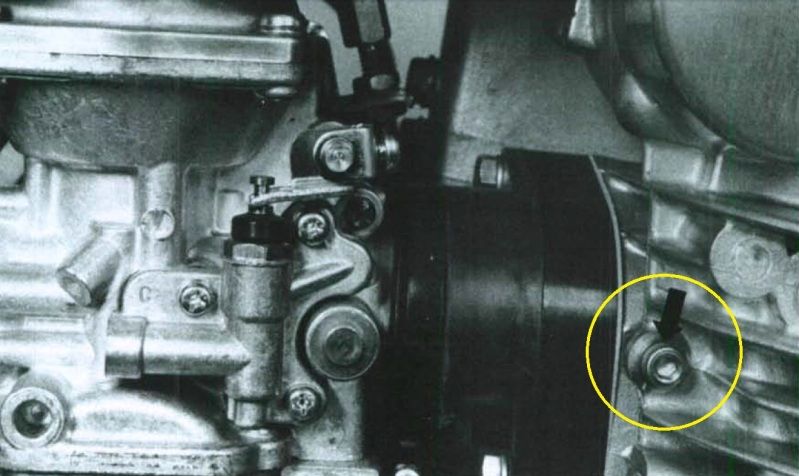
              I use the mark I've circled to line up the F marks for the timing. Is this wrong? the manual says to use other marks inside the inspection window but im pretty sure there isnt anything in there to line up with.

              Comment


                #37
                If memory serves correct you should be using a T mark not an F mark... I think... man I hope someone confirms this! I get myself all confused with these...
                1982 GS450E - The Wee Beastie
                1984 GSX750S Katana 7/11 - Kit Kat - BOTM May 2020

                sigpic

                450 Refresh thread: https://www.thegsresources.com/_foru...-GS450-Refresh

                Katana 7/11 thread: http://www.thegsresources.com/_forum...84-Katana-7-11

                Comment


                  #38
                  T is TDC, for cam timing. The F is where it should fire when it's not advanced at all. Rotate the big points plate to set timing on one set of points. This is done after the points gap or dwell is set.

                  And then the other set of points is timed the same way by moving the smaller plate.
                  http://img.photobucket.com/albums/v5...tatesMap-1.jpg

                  Life is too short to ride an L.

                  Comment


                    #39
                    Originally posted by tkent02 View Post
                    T is TDC, for cam timing. The F is where it should fire when it's not advanced at all. Rotate the big points plate to set timing on one set of points. This is done after the points gap or dwell is set.

                    And then the other set of points is timed the same way by moving the smaller plate.
                    Exactly, I think you're setting the points and thinking all that is left is hit it with a timing light, you have to do what Tom is saying here first, which is called static timing, basically when those points you gapped will start to open, when setting the gap, you just want to set them where the cam on the rotor opens them the widest, then set your static timing with the F mark, this was posted by someone here before, rather than find it, I saved a copy in pdf, I'm just going to copy/paste it here for you to read, save it for future use. This will cover replacing points and setting them up.


                    Installing and setting points
                    There is no difference between installing a Dyna electronic ignition and setting points and condensers. If you can do one, you can do the other. If you are having trouble with one, you will have the same trouble with the other. Learn to set the points and condenser ignition first. You will have to learn the process regardless. Here's the procedure for timing the 750. The points are located under the round cover on the right end of the crankcase/crankshaft. The round 6" plate that both sets of points are mounted on (breaker plate) is held in place by three screws located at 12, 4 and 8 o'clock. Loosen the 3 screws on the breaker plate. Note that the screw at 12 o'clock is in a slot. Rotate the breaker plate until the 12 o'clock screw is centered in the slot. Tighten the three screws. We will replace the left side set of points first (located at 9 o'clock position) These are the points for cylinders 1 and 4. Take a 19 mm wrench and rotate crankshaft until points are at widest gap. Unscrew hold down screw on pointset and remove points. Note the white wire that goes to the pointset and the placement of the insulator. The insulator must be correct or the points will be grounded out and will not work. Put the new points onto the breaker plate, set the gap to 14 thousandths, and lightly tighten the hold down screw. Install white wire. Rotate crankshaft once again with 19mm wrench until points are at widest gap. Check that widest gap remains at 14 thousandths. Adjust and re-tighten hold down screw if needed. Rotate crankshaft until right side points are at widest gap (for cylinders 2 and 3) Remove old points and install new points and set gap at 14 thousandths. Note insulators on black wire installation. Rotate crankshaft with 19 mm wrench again stopping at widest gap. Recheck gap as you did with the left pointset. Adjust and re-tighten hold down screw on points if needed. THE ABOVE COVERS SETTING THE POINTS GAPS Next is the timing: Timing for cylinders 1 and 4 (the left set of points).................... With 19 mm wrench, rotate crankshaft while looking through the timing window and align the mark that looks like F1| with the timing mark on the engine case.
                    (the line following F1 is the mark (|) note: some bikes will have a stationary timing mark on the engine case and some will have a mark on a stationary timing plate that can be seen through the timing window) Connect a continuity lights wire lead/clip to the white wire clip on the left pointset. Clamp continuity light probe tip to ground on the bike or battery negative terminal. Turn ignition switch to on (do not attempt to start bike, just switch ignition to on) The continuity light should be on. Loosen the three screws on the breaker plate located at 12, 4 and 8 o'clock. Rotate breaker plate until continuity light just flickers out. Re-tighten the 12, 4, and 8 o'clock screws on the breaker plate. Unclasp continuity lead from left pointset. For the Right pointset Rotate crankshaft with wrench until you see the timing mark F2| become aligned with the stationary timing mark on the engine case. Connect continuity light lead to black wire on right pointset. The ignition should be switched on and the continuity light should be on. The right pointset is mounted to a breaker half plate. You will see that you can loosen the mounting screws on this breaker half plate and this will allow you to move the right pointset. This will adjust the timing without changing the points gap. When you rotated the complete breaker plate for the left pointset to get the continuity light to flicker out, that's what you did. You adjusted the timing on cylinders 1 and 4 without changing the gap on their pointset. Unfortunately, the whole breaker plate being rotated moves BOTH sets of points, so that is why you must set the left side first and that is why the right side is mounted on its own independent half breaker plate. SOoooo.... Smile Loosen the breaker half plate on the right side and rotate as needed to cause the continuity light to just flicker out. Tighten the half plate back down when satisfied with the adjustment. Smile Remove continuity light and HOPEFULLY, start bike..
                    edit;
                    Ahhh, found it, this was posted by earlfor in tips and tricks section, he had found it in another forum
                    Last edited by Guest; 01-11-2013, 09:51 AM.

                    Comment


                      #40
                      I have done this process using a continuity tester on my multimeter and then verified it using my timing light.

                      My question is am I supposed to be lining up the F mark with the notch I circled in the photo in my previous post. This is the only marking I can find to line everything up against.

                      Comment


                        #41
                        I finally got the condensers on the mail and I've installed them. Now she revs out to redline no troubles.
                        Right cylinder still doesn't idle by itself so ill be vacuum testing to get the sync right. Just need to figure out where the vacuum guage plugs into now.

                        Comment


                          #42
                          Originally posted by jave101 View Post
                          Right cylinder still doesn't idle by itself so ill be vacuum testing to get the sync right. Just need to figure out where the vacuum guage plugs into now.
                          Do you not have a service manual for your bike?

                          If you don't, go to BassCliff's site (which you should have bookmarked), go to the Manuals section and get a copy of the Clymer manual for your bike.

                          Once you download AND SAVE the manual, you will find the carb sync procedure starting on page 41 in the manual (it's page 44 of the pdf).

                          There is a picture on page 42 that shows the location where you will attach your gauge, here it is, with the location highlighted:


                          .
                          sigpic
                          mine: 2000 Honda GoldWing GL1500SE and 1980 GS850G'K' "Junior"
                          hers: 1982 GS850GL - "Angel" and 1969 Suzuki T250 Scrambler
                          #1 son: 1986 Yamaha Venture Royale 1300 and 1982 GS650GL "Rat Bagger"
                          #2 son: 1980 GS1000G
                          Family Portrait
                          Siblings and Spouses
                          Mom's first ride
                          Want a copy of my valve adjust spreadsheet for your 2-valve per cylinder engine? Send me an e-mail request (not a PM)
                          (Click on my username in the upper-left corner for e-mail info.)

                          Comment


                            #43
                            Thanks for that Steve. I've got a manual just haven't gotten around to reading up on that just yet. Not a rush because the vacuum guage is still on it way.

                            Comment

                            Working...
                            X