Announcement
Collapse
No announcement yet.
Fusebox Melted - Advice Needed from Electrical Gurus
Collapse
X
-
 850GT_Rider
 -
 Suzuki_Don
As usual Jim you are right on the ball - yes that is insulation protecting the top part of the fusebox that is live. A piece of cloth covered fuel pipe split down it's length actually.Originally posted by posplayr View PostDon,
I don't quite understand your connections or what you mean by the fuse for controlling the R/R charging? Generally you need a 15 amp fuse between the battery and the rest of the electrical system, because if anything in the electrical system shorts the battery can supply many amps to that short. Under normal operation you don't need more that 15 amps an so that is why that fuse is selected,
If there is resistance the easiest way top find it is using a volt meter. Run the electrical and look for voltage drops where there should be none; those will hot
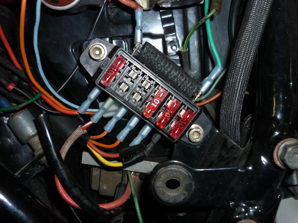
Jim I'll explain my wiring to you and get your approval hopefully. Looking at pics I have posted you will see a red wire coming into the fusebox at the top left is the power source from the solenoid (battery).
The power then goes through a 15A fuse to a red wire exiting at the bottom left of the fusebox.. This wire goes through the loom to the ign switch. When the ign switch is turned ON the power comes back to the fusebox via the green wire at the top right which feeds the ganged lower four RH fuses.
From right to left: Yellow wire - RH handlebar switch, to lights and instrument panel, etc. Red wire blue stripe - turn signal relay and blinkers. Orange wire - oil & neutral lights, both brake light switches & horn. Orange/white wire - kill switch, starter button, coil relay & Dyna S.
The other connection is the R/R+ wire coming at the bottom 2nd in from the left which feeds through a 10A fuse which is ganged to the left hand fuse and goes back to the battery via the wire to the solenoid.
I would like comments Jim if you see any issues with the way this is wired.
I now plan to put an inline fuse in place going from the R/R+ to the battery as Dan suggested. I do not have any accessories like hand warmers, etc. Not brought up on that sort of stuff. Can you see any issues with that inline fuse?
Also should I put dialectric grease on the fuses where they plug into the fuse box. If so how often should I do this to prevent high resistance
Thanks.Last edited by Guest; 06-08-2013, 04:05 AM.
Comment
-
Don,Originally posted by Suzuki_Don View PostAs usual Jim you are right on the ball - yes that is insulation protecting the top part of the fusebox that is live. A piece of cloth covered fuel pipe split down it's length actually.
Jim I'll explain my wiring to you and get your approval hopefully. Looking at pics I have posted you will see a red wire coming into the fusebox at the top left is the power source from the solenoid (battery).
The power then goes through a 15A fuse to a red wire exiting at the bottom left of the fusebox.. This wire goes through the loom to the ign switch. When the ign switch is turned ON the power comes back to the fusebox via the green wire at the top right which feeds the ganged lower four RH fuses.
From right to left: Yellow wire - RH handlebar switch, to lights and instrument panel, etc. Red wire blue stripe - turn signal relay and blinkers. Orange wire - oil & neutral lights, both brake light switches & horn. Orange/white wire - kill switch, starter button, coil relay & Dyna S.
The other connection is the R/R+ wire coming at the bottom 2nd in from the left which feeds through a 10A fuse which is ganged to the left hand fuse and goes back to the battery via the wire to the solenoid.
I would like comments Jim if you see any issues with the way this is wired.
I now plan to put an inline fuse in place going from the R/R+ to the battery as Dan suggested. I do not have any accessories like hand warmers, etc. Not brought up on that sort of stuff. Can you see any issues with that inline fuse?
Also should I put dialectric grease on the fuses where they plug into the fuse box. If so how often should I do this to prevent high resistance
Thanks.
Schematics are always best. . Attached is basically what I think you have. The next post is a recommendation. I think what you have is OK except:
a.) Not sure there is any reason for connecting the battery through one fuse to the R/R and another to the ignition switch.
b.) Second are you running the coil relay power through the ignition switch? A coil relay is a good compromise on reducing the power through the ignition switch but only using one relay controlled by the kill switch. The ignition switch now only has to carry about 1/2 the current it normally would.
Jim
Comment
-
 Suzuki_Don
Thanks Jim, much appreciated.
BTW when I rebuilt the wiring loom I fitted new 15A earth wires thoughout as well as the wiring going from fusebox to ign switch and from ign back to fusebox.
Comment
-
 850GT_Rider
I noticed that about the OE circuit too - the wiring from the R/R to the ignition switch (red) and back to the fuse box (orange) is therefore unprotected by fuse(s)?Originally posted by posplayr View PostThis one is closer to the OEM charging single point "T" configuration but includes the ignition relay mod.
Comment
.png)

Comment