Announcement
Collapse
No announcement yet.
Fusebox Melted - Advice Needed from Electrical Gurus
Collapse
X
-
Don't Remember Drops
Hmmm...you would ask me that. I don't remember. Are you talking about going from idle to 5K rpms?Originally posted by posplayr View PostThat is a good high number, more than most. However just to humor me what were your voltage drops at 5K?
EdGS750TZ V&H/4-1, Progressive Shocks, Rebuilt MC/braided line, Tarozzi Stabilizer[Seq#2312]
GS750TZ Parts Bike [Seq#6036]
GSX-R750Y (Sold)
my opinion shouldn't be taken as gospel or in any way that would lead you to believe otherwise (30Sep2021)
Comment
-
Revised Phase A in this postOriginally posted by GSXR7ED View PostHmmm...you would ask me that. I don't remember. Are you talking about going from idle to 5K rpms?
Ed
Comment
-
I have it printed
Originally posted by posplayr View Post
I'll just have to read it carefully to understand what you're asking. I was happy that it met the requirements. (14.0-14.8)
By knowing what you're asking of the results, what are you looking for? Is that written in the Phase A write up as well?
I'll read the print out when I get home later tonite since I can't get to the hyperlink on the reference thread atm.
EdLast edited by GSXR7ED; 06-05-2013, 06:14 PM.GS750TZ V&H/4-1, Progressive Shocks, Rebuilt MC/braided line, Tarozzi Stabilizer[Seq#2312]
GS750TZ Parts Bike [Seq#6036]
GSX-R750Y (Sold)
my opinion shouldn't be taken as gospel or in any way that would lead you to believe otherwise (30Sep2021)
Comment
-
Oh Yeah...
I thought about doing this but didn't know which was the red output wire for the R/R as well as the black output.Originally posted by posplayr View Post
Like I said, I was just happy that it was charging within the 14.0-14.8
EdGS750TZ V&H/4-1, Progressive Shocks, Rebuilt MC/braided line, Tarozzi Stabilizer[Seq#2312]
GS750TZ Parts Bike [Seq#6036]
GSX-R750Y (Sold)
my opinion shouldn't be taken as gospel or in any way that would lead you to believe otherwise (30Sep2021)
Comment
-
 Suzuki_Don
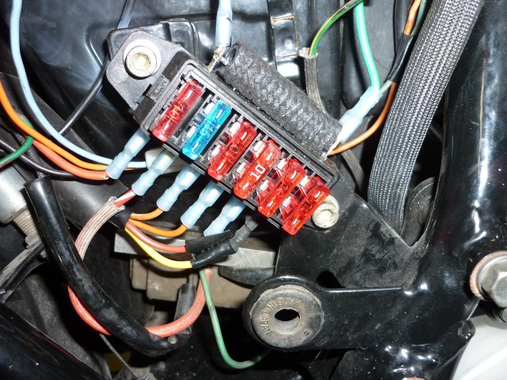
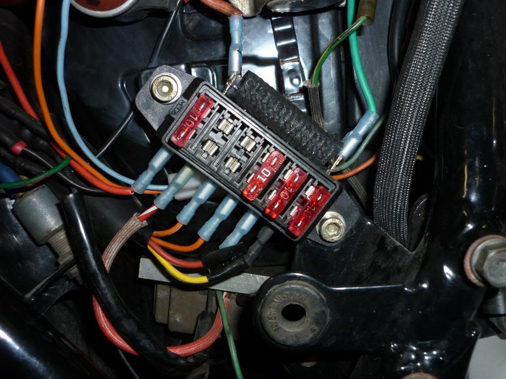
Well, new fuse box has been installed and I hope this doesn't happen again.

I've installed a 15A fuse as the MAIN and all other fuses are now 10A including the fuse that controls the R/R charging to battery.
EDIT: The above picture shows the two left hand fuses in the incorrect positions. They should be swapped around so the 15A fuse is on the MAIN circuit and the 10A (red) fuse is on the R/R charging circuit. I have since swapped these fuses around.
Although the fuse box melted on the input side of the fuse box and it would seem this high current did not actually pass through the fuse, so maybe the fuse would not have blown anyway no matter what amperage the fuse was. All conjecture I know.
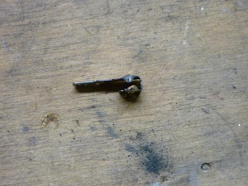
This is what is left of the fuse terminal I prised out of the melted fuse box.

Jim: I know you said it would have been a dirty connection between the fuse blade and the fuse box terminal, but do you think it could have been a loose fit between the fuse blade and the piece it fits into in the fuse box. If there was a loose fit that would have caused arcing and heat build up. What do you think. And if that was the case, how can I prevent this from happening in the future? Can I tin the metal blades of the fuse to make them a bit thicker and put more mechanical pressure on the connections from the fuse to its corresponding connection in the fuse box? I don't think there is anyway of compressing the terminals inside the fuse box to put more pressure on the connection.

What do you think?
P.S. Jim there are no connections that can be soldered in this fusebox.Last edited by Guest; 06-07-2013, 07:49 AM.
Comment
-
^^Looks good to me...you have skills with electrical stuff on your bike.
EdGS750TZ V&H/4-1, Progressive Shocks, Rebuilt MC/braided line, Tarozzi Stabilizer[Seq#2312]
GS750TZ Parts Bike [Seq#6036]
GSX-R750Y (Sold)
my opinion shouldn't be taken as gospel or in any way that would lead you to believe otherwise (30Sep2021)
Comment
-
everything has been detailed ad nauseam You don't want Voltage drops with a shunt R/R.Originally posted by GSXR7ED View PostI'll just have to read it carefully to understand what you're asking. I was happy that it met the requirements. (14.0-14.8)
By knowing what you're asking of the results, what are you looking for? Is that written in the Phase A write up as well?
I'll read the print out when I get home later tonite since I can't get to the hyperlink on the reference thread atm.
Ed
Comment
-
Don,Originally posted by Suzuki_Don View PostWell, new fuse box has been installed and I hope this doesn't happen again.

I've installed a 15A fuse as the MAIN and all other fuses are now 10A including the fuse that controls the R/R charging to battery.
EDIT: The above picture shows the two left hand fuses in the incorrect positions. They should be swapped around so the 15A fuse is on the MAIN circuit and the 10A (red) fuse is on the R/R charging circuit. I have since swapped these fuses around.
Although the fuse box melted on the input side of the fuse box and it would seem this high current did not actually pass through the fuse, so maybe the fuse would not have blown anyway no matter what amperage the fuse was. All conjecture I know.
This is what is left of the fuse terminal I prised out of the melted fuse box.

Jim: I know you said it would have been a dirty connection between the fuse blade and the fuse box terminal, but do you think it could have been a loose fit between the fuse blade and the piece it fits into in the fuse box. If there was a loose fit that would have caused arcing and heat build up. What do you think. And if that was the case, how can I prevent this from happening in the future? Can I tin the metal blades of the fuse to make them a bit thicker and put more mechanical pressure on the connections from the fuse to its corresponding connection in the fuse box? I don't think there is anyway of compressing the terminals inside the fuse box to put more pressure on the connection.

What do you think?
P.S. Jim there are no connections that can be soldered in this fusebox.
I don't quite understand your connections or what you mean by the fuse for controlling the R/R charging? Generally you need a 15 amp fuse between the battery and the rest of the electrical system, because if anything in the electrical system shorts the battery can supply many amps to that short. Under normal operation you don't need more that 15 amps an so that is why that fuse is selected,
As far as what caused the melting, you will have to look closely at where the heat was coming from. The heat is due to the resistance coupled with current even if that current is normal. Plan and simple.
Power- watts = Voltage^2/Resistance
= Current^2*Resistance
= Current*Voltage
Take your pic they are all the same thing.
Dirty contact, loose contact that arcs a little and develops resistance getting hot and further oxidizing the surface.
If there is resistance the easiest way top find it is using a volt meter. Run the electrical and look for voltage drops where there should be none; those will hot
Comment
-
I'll Try To Figure It Out
So, I can disconnect the R/R wires independently and apply the instructions given?Originally posted by posplayr View Posteverything has been detailed ad nauseam You don't want Voltage drops with a shunt R/R.
The POSITIVE RED wire coming rom the R/R is located under the seat area. For the Negative, can I just put the contact on the gounded Black wire?
I'm a little reluctant to do this because I don't want to mess anything up and not be able to ride.
Ed
EDIT: I'm reading a couple of reference points and trying to understand how this charging system works:
.png) Technical Info posts that are deemed to be important or popular will be placed here for easier access. If you feel a post should be moved from the Technical Info forum to here then PM the Administrator with your request.
Technical Info posts that are deemed to be important or popular will be placed here for easier access. If you feel a post should be moved from the Technical Info forum to here then PM the Administrator with your request.
Last edited by GSXR7ED; 06-07-2013, 09:21 PM.GS750TZ V&H/4-1, Progressive Shocks, Rebuilt MC/braided line, Tarozzi Stabilizer[Seq#2312]
GS750TZ Parts Bike [Seq#6036]
GSX-R750Y (Sold)
my opinion shouldn't be taken as gospel or in any way that would lead you to believe otherwise (30Sep2021)
Comment
-
Forum LongTimerGSResource Superstar
Past Site Supporter- Oct 2006
- 13969
- London, UK to Redondo Beach, California
I imagine his setup is like mine... I have a 15amp fuse in the stock position that goes between the battery & the rest of bike on the "output side".
I have a stand-alone fuse (on a short pigtail) going between the +ve on the RR & the battery +ve terminal. If I remember correctly that one is a 30amp fuse. (I've tried 20amp fuses with the Shindengen RR before & they blew).
I've run it that way for 2 years+
Earlier this year I moved to the SH775 series RR but I haven't changed anything, just plugged it in where the old one was & mounted it the same.
Eventually I might fit one of these. I prefer it to the Eastern Beaver version. You can always switch the circuits over (just by moving the fuse) if the onboard relay goes out to get you home & that relay would be easy enough to replace on the board.
 The FZ-1 is a uniquely designed compact fuse block. With its onboard relay, you have the choice for each accessory to have constant power or turn on or off automatically with your vehicle. Its 6 individually fused circuits that can be easily configured simply by moving the fuse to a different position on the board. Its compact design makes it a great choice for motorcycles. Fuzeblocks.com also offers our own high quality universal wire harness kits to further simplify installation. USA made.
Dan 1980 GS1000G - Sold
1978 GS1000E - Finished!
1980 GS550E - Fixed & given to a friend
1983 GS750ES Special - Sold
2009 KLR 650 - Sold - gone to TX!
1982 GS1100G - Rebuilt and finished. - Sold
2009 TE610 - Dual Sporting around dreaming of Dakar..... - FOR SALE!
www.parasiticsanalytics.com
TWINPOT BRAKE UPGRADE LINKY: http://www.thegsresources.com/_forum...e-on-78-Skunk/
Comment
-
nothing is disconnected, you just measure from the closest connection to the R/R to the center of the battery post for the red side and the black side.Originally posted by GSXR7ED View PostSo, I can disconnect the R/R wires independently and apply the instructions given?
The POSITIVE RED wire coming rom the R/R is located under the seat area. For the Negative, can I just put the contact on the gounded Black wire?
I'm a little reluctant to do this because I don't want to mess anything up and not be able to ride.
Ed
It should be obvious that if your R/R is connected right to the battery, then in theory the voltages are the same. That is however seldom true which is the source of the problems.
Comment
-
I know you are getting away with it, but from your description you could theoretically be pulling 30 amps on one fuse and 15 amps on the other and blow neither. That is 3 times stockOriginally posted by salty_monk View PostI imagine his setup is like mine... I have a 15amp fuse in the stock position that goes between the battery & the rest of bike on the "output side".
I have a stand-alone fuse (on a short pigtail) going between the +ve on the RR & the battery +ve terminal. If I remember correctly that one is a 30amp fuse. (I've tried 20amp fuses with the Shindengen RR before & they blew).
I've run it that way for 2 years+
Earlier this year I moved to the SH775 series RR but I haven't changed anything, just plugged it in where the old one was & mounted it the same.
Eventually I might fit one of these. I prefer it to the Eastern Beaver version. You can always switch the circuits over (just by moving the fuse) if the onboard relay goes out to get you home & that relay would be easy enough to replace on the board.
 The FZ-1 is a uniquely designed compact fuse block. With its onboard relay, you have the choice for each accessory to have constant power or turn on or off automatically with your vehicle. Its 6 individually fused circuits that can be easily configured simply by moving the fuse to a different position on the board. Its compact design makes it a great choice for motorcycles. Fuzeblocks.com also offers our own high quality universal wire harness kits to further simplify installation. USA made.
Dan
 . There is plenty of room to burn wires that way especially grounds.
Comment
-
On my Compufire RR it was provided with a 40a inline fuse and is connected directly to the battery positive post, sound alright?Originally posted by posplayr View PostI know you are getting away with it, but from your description you could theoretically be pulling 30 amps on one fuse and 15 amps on the other and blow neither. That is 3 times stock . There is plenty of room to burn wires that way especially grounds.1980 GS1000E
Comment
-
There are basically two ways to do it:Originally posted by mustangflyr View PostOn my Compufire RR it was provided with a 40a inline fuse and is connected directly to the battery positive post, sound alright?
1.) reconnect the R/R like the harness was designed. When you do this you need to make sure that the other connections (like fuse box) do not have too much resistance. When you do this you can rely on the 15 amp fuse in the fuse box.
2.) You can connect the R/R (+) directly to the battery (I don't do this ) people then generally just leave the original red wire to the harness open (taped back so it will not short). Experience has show you then need to increase the in line fuse from 15 amps to 20 amps and Dan is saying he needs 30 amps.
Lower amperage fuse is better if you can keep it from blowing as it will catch a short sooner. The fuse is to stop the battery from dishing out 50-100 amps in the case of a short (it has nothing to do with the power rating of the Compufire; the stator can not support 40 amps ).
You don't need to use a 40 amp fuse, that is basically like not having a fuse as much of the wire in your harness probably wont be too happy carrying 40 amps. Drop down to 20 amps and see if it blows, carry a 25 amp fuse just in case.
Dan may need 30 amp fuses as he has several accessories like heated gloves.
Comment
.png)

Comment