.png "Powered by vBulletin")
reg/rec
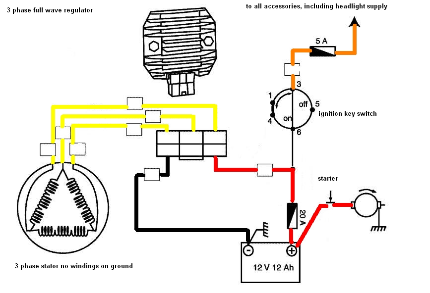
Hi, tonyp884. Your stator could be ok, the 2 wires left are a cicuit through the light switch and are not needed after the re-wire using a unit reg/rec instead of the seperate old units. I would think you are buying a 5 wire unit-3 wires from the stator and an earth + a live. If you unplug all wires from the regulator and rectifier, remove them from the bike. Find the 3 wires from the stator, they will be together in one sleave. You can test these as in the stator papers with a multi meter. This 3 wires conect to your new reg/rec, they could be all yellow or the same as the wires from the stator. Conect the earth ring terminal to 1 of the reg/rec mount bolts, the other mount bolt conect an earth wire from here to a GOOD earth elswhere. The red from the reg/rec conects to the fuse box. Then you will find you have 2 wires left, thats the loop to the light switch tape them up out of the way. I have 3 GS bikes a 77 750 - 78 550 - 79 1000. Thay all have had charge problems including melted wires and a small fire on the 1000, none of the stators have been replaced and all show good voltage with the engine running. As has been said read the stator pages from the garage link on the home page, and buy a multi meter. Have fun .
.
Hi, tonyp884. Your stator could be ok, the 2 wires left are a cicuit through the light switch and are not needed after the re-wire using a unit reg/rec instead of the seperate old units. I would think you are buying a 5 wire unit-3 wires from the stator and an earth + a live. If you unplug all wires from the regulator and rectifier, remove them from the bike. Find the 3 wires from the stator, they will be together in one sleave. You can test these as in the stator papers with a multi meter. This 3 wires conect to your new reg/rec, they could be all yellow or the same as the wires from the stator. Conect the earth ring terminal to 1 of the reg/rec mount bolts, the other mount bolt conect an earth wire from here to a GOOD earth elswhere. The red from the reg/rec conects to the fuse box. Then you will find you have 2 wires left, thats the loop to the light switch tape them up out of the way. I have 3 GS bikes a 77 750 - 78 550 - 79 1000. Thay all have had charge problems including melted wires and a small fire on the 1000, none of the stators have been replaced and all show good voltage with the engine running. As has been said read the stator pages from the garage link on the home page, and buy a multi meter. Have fun
.

Comment