He covered all the bases and I'm sure he sent you pictures in emails that covered this in some way.
Announcement
Collapse
No announcement yet.
Solid State Power Box STANDARD INSTALLATION
Collapse
X
-
I may be sensitive since Jim is my friend and I saw the grueling effort he put forth creating this.
He covered all the bases and I'm sure he sent you pictures in emails that covered this in some way.1983 GS 1100E w/ 1230 kit, .340 lift Web Cams, Ape heavy duty valve springs, 83 1100 head with 1.5mm oversized SS intake valves, 1150 crank, Vance and Hines 1150 SuperHub, Star Racing high volume oil pump gears, 36mm carebs Dynojet stage 3 jet kit, Posplayr's SSPB, Progressive rear shocks and fork springs, Dyna 2000, Dynatek green coils and Vance & Hines 4-1 exhaust.
1985 GS1150ES stock with 85 Red E bodywork.

-
The SSPB is not a form factor replacement for the fuse box on every GS motorcycle ever produced. I'm sure that was not stated, but apparently it bears clarification.Originally posted by Sci85 View PostMake everyone aware who has a 550 model that some modification is necessary to fit the SSPB. It will not go into the factory location like the pictures of the 1100.
I don't see how in the world you can read anything more than that into my post. Oh well, some people...
And Jim, yeah, I think once I move that stuff it will work. I didn't realize at first that the left hand main fuse box was redundant. Thanks for pointing that out.
The SSPB is very close in form factor and fits in the stock location of all of the later GS 5 position blade fuse boxes with the diagonal tabs. These were used starting in about 1982 and continued (although there were some changes) into even the early 90s' on other Suzuki motorcycles.
There are apparently other tabless blade fuseboxes that are attached with plastic inserts, which is where the Tabless option comes from. I think exclusive of the tabs the fuse box was basically the same size.
There are also earlier glass fuse type fuse boxes that also have 5 circuits. Those are slightly smaller in size as the 5 position blade and they have horizontal tabs. The SSPB will generally fit in those locations also if ordered with the Horizontal heat sink tabs.
There are other old style mini fuse boxes with only 4 fuses which are much shorter, and even though the SSPB fits the same horizontal hole spacing, depending upon where those are located, the SSPB may not fit in the same location(as Sci85 has discovered). Depending upon the bike, these small fuse boxes can be located very close to the frame requiring relocation of the mounting holes for the SSPB to fit.
Generally having to more the mounting holes is not a show stopper as in Sci85's case there are two elements being removed (clearing space)and shoehorning in an SH-775 with OEM connectors requires enough creativity that the SSPB fitment becomes a minor issue.
For anybody considering a purchase you should look at your current fusebox location and or/or send me a picture to best determine how to fit it.
Here is a link describing the SSPB size.
here are the mounting options.
P.S. I need to fix the figure, the Tabless uses studs and is not threaded as shown. The heatsink is the same thickness for all.Here are the 3 mounting options;
- Diagonal tabs
- Symmetrical tabs
- Tabless
I also added another option for tabless mounting where you have to drill through your mounting plate and screw in from the back.

Here is a link with discussion on size and the three fuse boxes described above.
Last edited by posplayr; 03-08-2014, 09:55 PM.
Comment
-
Thanks Bill, but I guess it is hard to find all of the detail given all the descriptions. It is spread around a bit.Originally posted by chef1366 View PostI may be sensitive since Jim is my friend and I saw the grueling effort he put forth creating this.
He covered all the bases and I'm sure he sent you pictures in emails that covered this in some way.
I will have to do some more clean up I guess.
If anybody has any more questions, ask me here or at solidstatepowerbox@gmail.com. Last edited by posplayr; 03-08-2014, 09:56 PM.
Comment
-
Solid State Power Box
Posplayr,
How much $ is the SSPB? I ride an 1100EZ (yours is ED, right?). Is it a replacement for the stock fuse box? I'm very much a newbie at wrenching on bikes, but someone (Chef?) said he noticed it made his lights brighter, and that caught my eye.
How is it related to the rectifier/regulator, which many have suggested should be upgraded from stock?1982 GS1100E V&H "SS" exhaust, APE pods, 1150 oil cooler, 140 speedo, 99.3 rear wheel HP, black engine, '83 red
2016 XL883L sigpic Two-tone blue and white. Almost 42 hp! Status: destroyed, now owned by the insurance company. The hole in my memory starts an hour before the accident and ends 24 hours after.
Comment
-
The SSPB although is pretty much customized for the later model Suzuki's it is applicable to most all of the non fuel injected bikes that have 4 primary electrical circuits (SIGNAL,HEADLAMP,IGNITION,ACCESSORY).Originally posted by Rob S. View PostPosplayr,
How much $ is the SSPB? I ride an 1100EZ (yours is ED, right?). Is it a replacement for the stock fuse box? I'm very much a newbie at wrenching on bikes, but someone (Chef?) said he noticed it made his lights brighter, and that caught my eye.
How is it related to the rectifier/regulator, which many have suggested should be upgraded from stock?
It is pretty much a universal recommendation now at teh GSR to use a Series R/R and teh SH-775 is the least expensive way to get there. The next step to improving your electrcial can take many forms, but what I did is design the best of that into a singel solid state device that replaces teh stock fuse box. You can read about the benefist here.
For a GS1100E that you want to renew and ride for a long time , I would recommend the SSPB along side of a Series R/R because by marrying the two together at the same time you basically will never have to worry about charging and charging connections again. Here is a simplified description of the benefits.
Here are two pictures of the GS110EZ/ED one with the Compufire and SSPBThe Solid State Power Box (SSPB) is a new product designed to improve on the original electrical system of your motorcycle by providing better and safer distribution of that power. What is power distribution? Power distribution is how the electrical power in your motorcycle is routed from its’ sources (i.e. your battery and alternator) to the various electrical components located on your bike. Electricity travels in circuits; the power has to start at a source, get distributed to the loads and then return back to the source to complete that circuit. The SSPB was designed with the whole electrical system in mind. The SSPB was designed to minimize if not eliminate all of the following types of chronic problems motorcycle electrical systems typically experience.- Dirty and melted fuse box contacts
- Blown fuses and replacement of same.
- Hard to find shorts.
- Dirty and melted IGN/KILL/START switches.
- Excessive Voltage drops to coils, headlamps, horns.
- Poor charging due to circuitous R/R to Battery connections.
- Mysteriously failed components from current surges and voltage spikes.
- Marginal wire sizes.
- Lack of proper grounding.
- Limited space
- unwieldy size of traditional fixes for the list above.
As an example, during the resto-mod of my GS1100ED, I replaced the electrical system with all brand new OEM harness and OEM switches. Within a couple of years I still needed to install a coil relay modification as the bike was hard to start due to low voltage to the coil. This is just one of the classic symptoms of a “simple” motorcycle power distribution DESIGN. The electrical systems of these older bikes are quite similar, and given the technology of the day, the designs were probably the lessor of other evils namely design complexity and unreliability.
Many of you in fact have firsthand knowledge of many of the chronic problems listed above. But while the problems may be understood, it is also understandable that without an engineering background it is probably harder to understand how the SSPB does anything to improve on the list of chronic problems. The SSPB was designed to be unobtrusive and so it was made to fit in place of the stock fuse box. So one might guess that the SSPB is just a better fuse box, but in fact as I have alluded to above, the SSPB does much more than just get rid of fuses. The SSPB improves the general electrical and charging health of your motorcycle by re configuring the overall power distribution of the original design.
The SSPB is not entirely unique in this approach, as there are several fuse box products available on the market that were designed to address at least some of these same classic motorcycle distribution issues. Most aftermarket fuse box and power distribution products you see on the market are after the same thing, improving power distribution and reducing if not solving the issues that stem from the original design problems. The SSPB is also designed to solve those problems but does so in a more comprehensive way and has additional features available from modern automotive grade electronics and design that have never been incorporated into the other products.
Most of the newer product solutions today, are adding into the old electrical system what most motorcycle designers avoided back in the day (relays combined with the fuse boxes). The main reasons they were avoided was the size and unreliability of mechanical relays. As technology has advanced, newer fuse box products offer a single mechanical relay for power distribution which is now more reliable, but still quite bulky. Some products add banks of mechanical relays, but then space generally becomes an issue. Adding a bank of relays and a fuse box with associated connectors takes a lot of real estate and generally more than is available. While there have been improvements, it is still old technology and it has definite limitations.
On the other hand the SSPB which uses solid state automotive technology can implement a full complement of electronic relays using what can only be called "smart switch" technology. This allows the SSPB to implement all the relay functions that were previously needed but get them to fit inside the same space as the original fuse box but without the need for the fuses. This solid state design is much more rugged and reliable than the old mechanical relays, and it all fits into the same space originally occupied by your fuse box.
Beyond the improved power distribution of the SSPB, probably the most important feature of the "smart switch" technology is what I have been calling "Safe Power". Once installed (i.e. all power routed through the SSPB from Battery and R/R) you won't have to worry about damaging anything from electrical shorts and if you do get a short it will be much easier to track it down.
You can short the output of any one of the SSPB channels and the SSPB will current limit to stop any demand for current over 10 amps and if the SSPB gets too hot it will thermal limit cycle . So as the demand (e.g. short goes away) the SSPB goes right back to delivering full current. No power resets required. So by providing "safe power" through current limiting and thermal limits, the need for a conventional fuse box goes away. It is replaced with a better form of power distribution that is only possible by using a new design approach that uses solid state “Smart Switch” electronics. All 5 SSPB channels have this capability.
- UNSWITCH (always on) – SSPB Red(0))
- SIGNAL CIRCUITS (O/G on GS Suzuki)
- IGNITION CIRCUITS (O/W on GS Suzuki)
- HEADLAMP CIRCUITS (O/R on GS Suzuki)
- SWITCHED Accessory – SSPB Red(2).
These 5 SSPB circuits match one for one the 4 primary circuits your existing harness has with an extra switched Red(2) for expansion. There is 50 amps of individual circuit capacity although the design limits the total current to the 15 amps which is what the GS needs.
The SSPB has the equivalent of "built in" relays in that you can control the distribution of 4 circuits using external switches rather than having to run the power through those switches. This means you don't have to worry about voltage drops through the IGN , KILL, Start buttons any more. There is also a feature to use a 4th switch to control another device of your choosing for extra driving lights, heater or other accessory. So there are built in IGNITION relays Modification, built-in (2of 3 relays) HEADLAMP relay Modification with startup cutout and at least up to 10 amps a Horn or other relay modification all included in the SSPB. If you are counting that is the equivalent of 5 Bosch type automotive relays all built into the SSPB.
In designing the SSPB, I looked to improve and streamline the final installations as compared to the installations of other offerings. This involved looking at how to optimize the power and grounding for all electrical power assuming a clean slate, as opposed to how to modify what was there. So the net result is that the SSPB is just as easy to connect up to your bike, and also has the benefits of being much easier to keep your charging system in good health. Connections between the R/R and Battery have been separated from the harness and have been simplified to give the best performance. If you couple the SSPB with a Series R/R you will have a very sophisticated and efficient electrical system that you won’t even find of much more modern bikes.
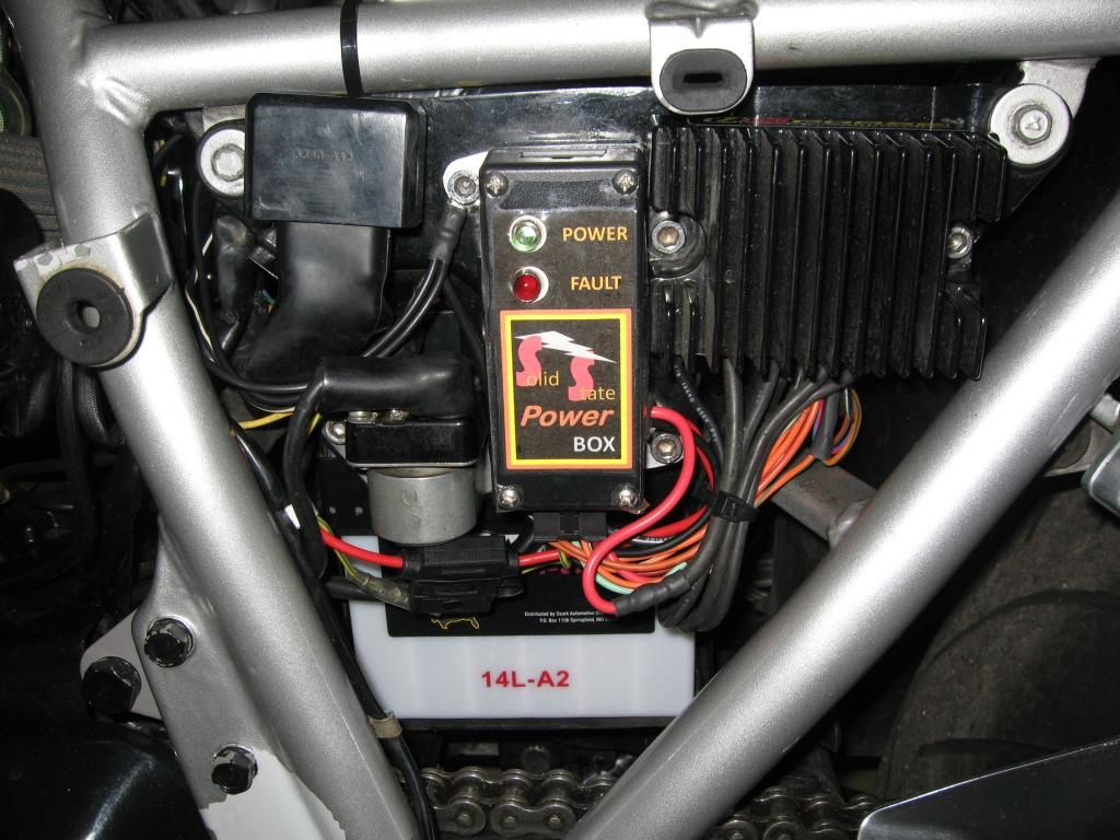
Here the SH-775 with room for teh SSPB to replace the stock fusebox.
[QUOTE=isleoman;1916213]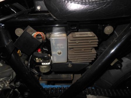
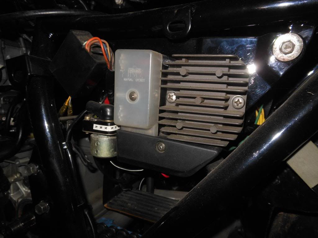
They are $150 for a 3 year warranty plus flat rate shipping/insurance to the US for $8. It is $13 to Canada. Email me at solidstatepowerbox@gmail.com.
I will take about a week to ship.
I have plenty of install guides and videos and will help with what you need to get it installed.
Comment
-
No worries all. I do run the SH-775 and I did have to get creative to install it. Currently, I am using the top of the air box with a modified cover. It fits there nicely.
For any self respecting DIY'er, this is not a show stopper. And I too appreciate all the effort Jim has put into this.
In the 550's case, it is very tight in there with the rear master cylinder creating some issues as well. I will have to detab the factory right hand side of the airbox to fit the SSPB in that location (hopefully). In retrospect, I probably should have ordered the tabless version. But again, that's my issue. I will try and document what I did and post up some pics so you can incorporate that into your documentation Jim if you like. I will put it into the SSPB installation thread unless you have another preference.
Thanks again.1982 GS550M Rebuilt Winter '12 - 550 to 673cc engine conversion.
1989 Kawasaki ZX-7 Ninja
2016 Ducati Scrambler Full Throttle
Comment
-
Not only the 550 but most motorcycles are tight for space, which was a primary driver in the SSPB design. There is just not a lot of room for wires, relays and connectors everywhere.Originally posted by Sci85 View PostNo worries all. I do run the SH-775 and I did have to get creative to install it. Currently, I am using the top of the air box with a modified cover. It fits there nicely.
For any self respecting DIY'er, this is not a show stopper. And I too appreciate all the effort Jim has put into this.
In the 550's case, it is very tight in there with the rear master cylinder creating some issues as well. I will have to detab the factory right hand side of the airbox to fit the SSPB in that location (hopefully). In retrospect, I probably should have ordered the tabless version. But again, that's my issue. I will try and document what I did and post up some pics so you can incorporate that into your documentation Jim if you like. I will put it into the SSPB installation thread unless you have another preference.
Thanks again.
If you find that you can't make the tabbed version work, I could build up another tabless version to swap it out.
Comment
-
Well...I decided to pull the trigger and get a new wiring harness for the GS (82 EZ). So many connections were corroded...plugs were brittle & cracked. The R/R plug? Egads it was corroded, rusty, nasty.
SO...after a few more bits are delivered and sorted, I will probably be buying an SSPB. Found the installation videos and have watched them a couple times already, lol.
With a new harness, I won't have to undo the coil relay mod, although I do have a Dyna S installed. I have also purchased 3.0 ohm Dyna 'green' coils as well.
I'm not sure the Ole Girl will know what to do with herself Mike
Mike
1982 GS1100EZ
Text messages with my youngest brother Daniel right after he was paralyzed:
Me: Hey Dan-O. Just wanted to say howdy & love ya!
Dan-O: Howdy and Love you too. Doing good, feeling good.
Me: Give 'em hell, Little Bro!
Dan-O: Roger that! :)
Comment
-
Make sure your clean all the mating connectors even if the main harness is new. This has been recommended here and I am using it religiously as it is much easier than dielectric grease.Originally posted by Cassius086 View PostWell...I decided to pull the trigger and get a new wiring harness for the GS (82 EZ). So many connections were corroded...plugs were brittle & cracked. The R/R plug? Egads it was corroded, rusty, nasty.
SO...after a few more bits are delivered and sorted, I will probably be buying an SSPB. Found the installation videos and have watched them a couple times already, lol.
With a new harness, I won't have to undo the coil relay mod, although I do have a Dyna S installed. I have also purchased 3.0 ohm Dyna 'green' coils as well.
I'm not sure the Ole Girl will know what to do with herself
You might also want to take the time now to go to LED's, I just sorted out a good set from the Amazon LED bargain basement. I'll have a small device to make your TCSU work pretty soon.
You will also want to do this.
And this
And this maybe
I'm also installing HID and a BadBoy/Wolo horn.
Other stuff but it is too much to list.
Comment
-
Not necessary Jim but thank you for the offer. I've already got it mounted and am working up soldering the connections. However, I have the benefit of using aftermarket filters so modding the factory airbox was not a problem. Others who are still using the stock filter might have a harder time. I ended up securing it from the inside with some nuts on the included bolts. Hope to finish up tomorrow and post up some pics if I got it right.If you find that you can't make the tabbed version work, I could build up another tabless version to swap it out.
I will say at this point so far, it's been fairly simple. 1982 GS550M Rebuilt Winter '12 - 550 to 673cc engine conversion.
1989 Kawasaki ZX-7 Ninja
2016 Ducati Scrambler Full Throttle
Comment
-
Ok Jim, got a question. I'm close to finished but one wire is giving me a particular hard time. I'm trying to determine what wire goes to the white, pin 3 on the SSPB. I checked my diagram and I do not have an O/G from the ignition switch. Mine shows only R,O,Gr,Br. Which wire is the correct on to hook up to pin 3? Or am I reading it wrong? BTW, I watched the video, part 2, but am a little confused.
And just a sanity check for me. All the O/x wires that come from the fuse box go to pins 7,10,9, and 8 yes?
Thanks!1982 GS550M Rebuilt Winter '12 - 550 to 673cc engine conversion.
1989 Kawasaki ZX-7 Ninja
2016 Ducati Scrambler Full Throttle
Comment
-
The Pin 3 on the SSPB needs an input from the Kill Switch. Note you will have to do a couple of changes at the Kill switch as well as you would with any coil relay mod.Originally posted by Sci85 View PostOk Jim, got a question. I'm close to finished but one wire is giving me a particular hard time. I'm trying to determine what wire goes to the white, pin 3 on the SSPB. I checked my diagram and I do not have an O/G from the ignition switch. Mine shows only R,O,Gr,Br. Which wire is the correct on to hook up to pin 3? Or am I reading it wrong? BTW, I watched the video, part 2, but am a little confused.
If you have rewired your stator to go direct to your R/R then there should be two spare wires in your harness, a Green/White (G/W) and a White/Red(W/R). We are going to re-purpose these wires to provide switch inputs to the SSPB from the front of the bike.
So unless you have already used, or have other plans for these two wires I would suggest finding where you cut them off (where the R/R connected to the harness) and extend them to the SSPB and connect as follows:
G/W wire to the WHITE Pigtail on the Molex which is connected to SSPB Pin3.
W/R wire to the GREEN Pigtail on the Molex which is connected to SSPB Pin2
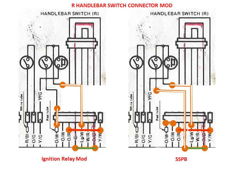
Go ahead an do that as shown in this figure and then we can move on to the Kill Switch mods.
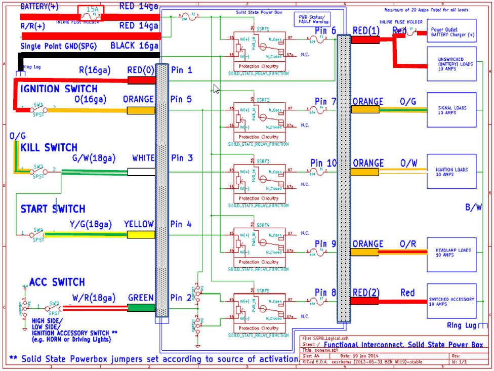
The kill switch needs to be powered from a switched power source there are several options but these are the primary ones.
The O wire coming from your ignition switch.
The O/G which is the SIGNAL circuit now being powered by the SSPB.
Here are the mods that should be easy to do in your headlamp bucket. It does two things:
It separates the kill switch from O/W and power the kill switchs from O/G.
Reroute the output of the kill switch to SSPB Pin 3 via the repurposed G/W wire.
The re purposed W/R can be connected to any switch you want for ACCESSORY control. If you don't have one at the moment just leave it open. This figure compares a standard Coil relay mod to the SSPB installation. The only difference is where the power to the Kill switch comes from.
Close, compare to the diagram above, this grouping of wires.Originally posted by Sci85 View PostAnd just a sanity check for me. All the O/x wires that come from the fuse box go to pins 7,10,9, and 8 yes?
Thanks!
CONNECT OLD WIRES:
O/G to ORANGE Pigtail is Pin 7 (New SSPB powered SIGNAL CIRCUIT)
O/W to ORANGE Pigtail is Pin 10 (New SSPB Powered IGNITION CIRCUIT)
O/R to ORANGE Pigtail is Pin 9 (New SSPB Powered HEADLAMP Circuit)
Red to RED Pigtail is Pin 1 (New SSPB Powered Un-switched Circuit to the IGN switch same as Pin 6)
O to ORANGE Pigtail is Pin 5 (IGN switch signal to power the SSPB)
CONNECT New wires :
G/W to White Pigtail to Pin 3 (from Kill switch output)
Y/G to Yellow Pigtail to Pin 4 (from starter solenoid)
W/R to Green Pigtail to Pin 2 (from spare accessory control wire)
Growth that you may or may not need:
Red pigtail to UN-SWITCHED POWER on Pin 6
Red pigtail to SWITCHED POWER on Pin 8Last edited by posplayr; 03-11-2014, 08:27 PM.
Comment
-
Jim, thank you so much for the help. I can handle basic electrical troubleshooting but I don't see circuits in my mind like smart folks. I need a visual from my specific wiring diagram so I don't screw it up. Could you replicate the Handlebar Switch Connector Mod diagram using my specific wiring diagram? I think that would help me a ton.
The wiring diagram is here:
https://my.syncplicity.com/share/w7x...2_Wiring_Color
Thanks again Jim.1982 GS550M Rebuilt Winter '12 - 550 to 673cc engine conversion.
1989 Kawasaki ZX-7 Ninja
2016 Ducati Scrambler Full Throttle
Comment
-
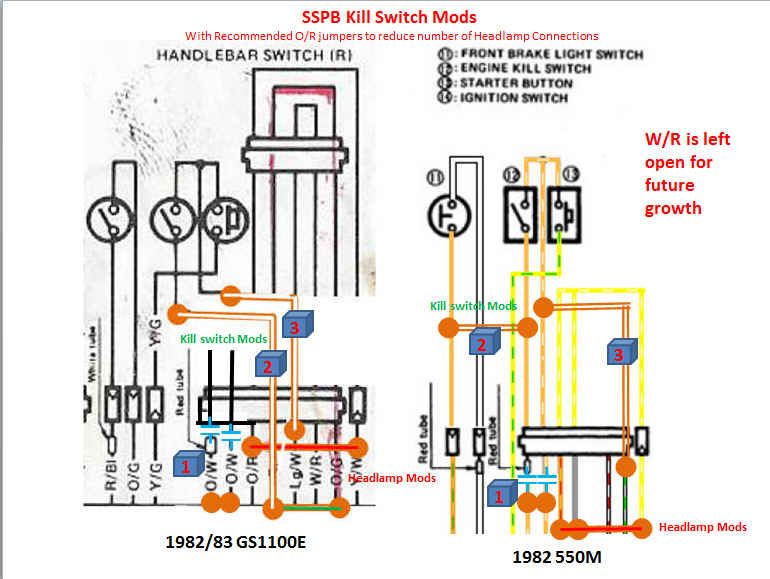
OK here is a side by side of the 82/83 GS1100ED Kill switch mods with the equivalent on the 82 550M colored schematic.Originally posted by Sci85 View PostJim, thank you so much for the help. I can handle basic electrical troubleshooting but I don't see circuits in my mind like smart folks. I need a visual from my specific wiring diagram so I don't screw it up. Could you replicate the Handlebar Switch Connector Mod diagram using my specific wiring diagram? I think that would help me a ton.
The wiring diagram is here:
https://my.syncplicity.com/share/w7x...2_Wiring_Color
Thanks again Jim.
For clarity (or not) I added the changes to the headlamp circuit as well, because while you are there this will further help the voltage to the headlamp. This is strictly to remove some unnecessary harness connections that Suzuki left it the harness that just creates a place to loose voltage to your headlamp and lights; it has nothing to do with the SSPB except after the SSPB is in, these unnecessary connection can represent one of the biggest voltage drops for the headlamp.
The 550 doesn't have a O/G on the same kill switch connector so I went over to the brake light switch to pick it up.
To summarize there are basically three modifications for the Kill switch
STEP 1.) Separate the Kill switch from it's existing two O/W connections to the harness and connect the two harness side wires together. The best place to do this is the two O/W wires ( on the harness side ) of the connector in the headlamp bucket. Cut the wires off close to the connector then strip them back and twist and solder them together with shrink tubing. They will be carrying the ignition circuit currents.
STEP #2 Power the Kill Switch input from the O/G (O/G is SIGNAL switched power).
STEP #3 Connect the output of the Kill Switch to the G/W to signal the SSPB on Pin 3
 Last edited by posplayr; 03-11-2014, 10:07 PM.
Comment
-
Thank YOU! That's exactly what I needed Jim. The visual makes all the difference in the world. Sucks I gotta go out of town tomorrow now
Hopefully she'll be ready by this weekends warmer weather!1982 GS550M Rebuilt Winter '12 - 550 to 673cc engine conversion.
1989 Kawasaki ZX-7 Ninja
2016 Ducati Scrambler Full Throttle
Comment
.png)
.png)

Comment