Announcement

Collapse
No announcement yet.

Can anyone Identify these 2 wires

Collapse
X
 
  • Filter
  • Time
  • Show
Clear All
new posts

    Can anyone Identify these 2 wires

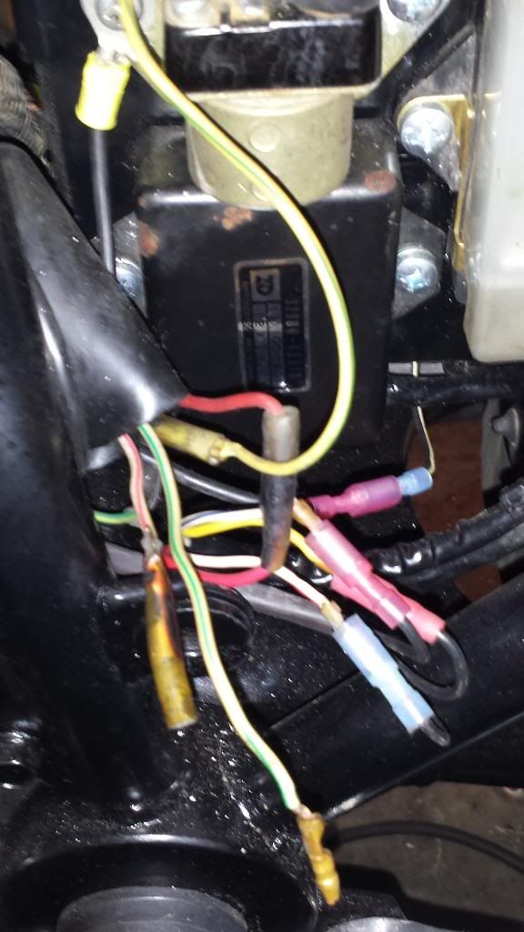
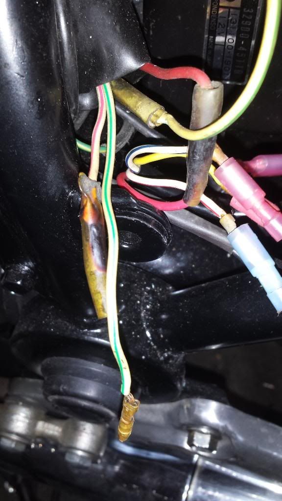
    I am almost done with my project and I have 2 wires that don't seem to have a match, as you can see from the pictures. These wires are in the main part of the loom and the bundle includes the wires for the stator.

    All the electrical systems of the bike work as they are supposed to. The bike charges at 14.06V, all the lights work etc. I chose not to connect them together since the colors are wrong. So I am baffled what these 2 wires are for. Any help anyone?

    #2
    Originally posted by bomber737 View Post
    I am almost done with my project and I have 2 wires that don't seem to have a match, as you can see from the pictures. These wires are in the main part of the loom and the bundle includes the wires for the stator.

    All the electrical systems of the bike work as they are supposed to. The bike charges at 14.06V, all the lights work etc. I chose not to connect them together since the colors are wrong. So I am baffled what these 2 wires are for. Any help anyone?
    Not exactly sure which wires you are referring to but I suspect it is the Lg/W and W/R. Those are the headlamp loop wires (a schematic is a terrible thing to waste ) . If you connected the R/R direct to the stator (as you should) then those are now spare wires.

    BTW that 14.06V will probably rise if you clean /replace that blackened red bullet connector. Got any DeOxit?

    Comment


      #3
      The connectors are clean on the inside, I pulled them apart and took a wire brush to all the males and a small round wire brush to the female connectors. I just didn't replace the sheathing when I put it back together. I will have to see if I can dig up a wire diagram. I'm just not the best at using them. I did connect the regulator to the stator directly, thats what the red/blue insulated connectors are at the bottom of the picture.
      Last edited by Guest; 02-20-2014, 08:37 PM.

      Comment


        #4
        Originally posted by bomber737 View Post
        The connectors are clean on the inside, I pulled them apart and took a wire brush to all the males and a small round wire brush to the female connectors. I just didn't replace the sheathing when I put it back together. I will have to see if I can dig up a wire diagram. I'm just not the best at using them. I did connect the regulator to the stator directly, thats what the red/blue insulated connectors are at the bottom of the picture.
        When people say to clean connectors, then do mean clean and they probably mistakenly mean with a brush. But to effective clean the connections that means chemically. DeOxit is safe and simple. Get a can. I have recommended Naval jelly in the past but the DeOxit is much easier. Just give it a little spray and let it do it's stuff with no need to wipe or clean anything other than over spray.

        Did you ever do the Revised Phase A part of stator pages to actually measure your voltage drops?
        Make sure you do these two tests and report the results for diagnosis.
        STEP #2 MEASURE POSITIVE LEAD VOLTAGE DROP
        STEP #3 MEASURE NEGATIVE LEAD VOLTAGE DROP


        Link to Revised PHASE A of Stator Pages:

        ORIGINAL_STATOR_PAGES

        The most important thing to do checks at 5000 RPM which is typical cruising speed. You might find that you will need to clean your fuse box to get the positive side voltage drops below 0.2V at 5000 RPM. In steps #1 above you should of gotten most of the connections between the R/R(+) to battery (+) in good shape except the fuse box.
        Last edited by posplayr; 02-20-2014, 09:25 PM.

        Comment


          #5
          I see, I did use the electronic cleaner you get at radio shack and sprayed all the connectors. I did not to the voltage test on the stator yet as I just go the bike running earlier this morning. In my opinion a charge of 14.06V is good. You want to see 13.7 to 14.8V in a charging system and this did not change when I turned on the high beam and turn signals and brake light at the same time. Much over 15V and you run the risk of cooking your battery by over charging it. I will be wiring a mini volt meter in so she can keep an eye on it while she is riding. I will also be replacing the regulator with one from Ricks but that has to wait till I can afford to get the seat re-contoured and a new cover made for it and get the side covers and tank painted.

          Comment


            #6
            Originally posted by bomber737 View Post
            I see, I did use the electronic cleaner you get at radio shack and sprayed all the connectors. I did not to the voltage test on the stator yet as I just go the bike running earlier this morning. In my opinion a charge of 14.06V is good. You want to see 13.7 to 14.8V in a charging system and this did not change when I turned on the high beam and turn signals and brake light at the same time. Much over 15V and you run the risk of cooking your battery by over charging it. I will be wiring a mini volt meter in so she can keep an eye on it while she is riding. I will also be replacing the regulator with one from Ricks but that has to wait till I can afford to get the seat re-contoured and a new cover made for it and get the side covers and tank painted.
            In my opinion 14.06V is marginal and suggestive of 1/2 volt drop in your system due to corrosion that certainly wont get any smaller and more than likely will get bigger.

            Also if you read up on Series R/Rs you will find there is something called an SH-775 and it would be better/cheaper to get that rather than a Rick's.

            Comment


              #7
              Not to go against Jim here, but physically scrubbing the terminals and pinching down the female socket is the best way to improve the joint. I've used Deoxit before and not sure if it's effective or not.
              Ed

              To measure is to know.

              Mikuni O-ring Kits For Sale...https://www.thegsresources.com/_foru...ts#post1703182

              Top Newbie Mistakes thread...http://www.thegsresources.com/_forum...d.php?t=171846

              Carb rebuild tutorial...https://gsarchive.bwringer.com/mtsac...d_Tutorial.pdf

              KZ750E Rebuild Thread...http://www.thegsresources.com/_forum...0-Resurrection

              Comment


                #8
                Originally posted by Nessism View Post
                Not to go against Jim here, but physically scrubbing the terminals and pinching down the female socket is the best way to improve the joint. I've used Deoxit before and not sure if it's effective or not.
                Ed it is hard to see how squeezing a crimp will decrease resistance in a crimp. I do agree if the female portion doesn't have enough tension to hold the male bullet then give it a squeeze.

                I have had bullets that I have brushed and cleaned and they still showed open using an ohm meter. Might have been an extreme case but for charging connections only 0.1ohms can be detrimental.

                Comment


                  #9
                  I just solder my stator wires , saves worrying about the connector being dirty. Whats the worst case scenario, may have to cut the wire and solder it again if you have a component failure .
                  1984 GS1100GK newest addition to the heard
                  80 GS 1000gt- most favorite ride love this bike
                  1978 GS1000E- Known as "RoadKill" , Finished :D
                  83 gs750ed- first new purchase
                  85 EX500- vintage track weapon
                  1958Ducati 98 Tourismo
                  “Remember When in doubt use full throttle, It may not improve the situation ,but it will end the suspense ,
                  If it isn't going to make it faster or safer it isn't worth doing

                  Comment


                    #10
                    I did my best to clean the connectors. Wire brush, electronic cleaner and I pulled them in and out a few times. All the connectors for the stater are new and the wires tinned, actually all the wires I put in the harness were tinned and if I didn't like the look of a connector I cut it off and replaced it. You can't get much cleaner than new. The only thing I can do more is put dialectic grease in them to prevent any future corrosion and perhaps some copper anti-seize to help with the connection.

                    Comment


                      #11
                      Originally posted by bomber737 View Post
                      I did my best to clean the connectors. Wire brush, electronic cleaner and I pulled them in and out a few times. All the connectors for the stater are new and the wires tinned, actually all the wires I put in the harness were tinned and if I didn't like the look of a connector I cut it off and replaced it. You can't get much cleaner than new. The only thing I can do more is put dialectic grease in them to prevent any future corrosion and perhaps some copper anti-seize to help with the connection.
                      DeOxit cleans and leaves a coating to prevent future corrosion. No need to pullout the dielectric grease.


                      Also those tests mentioned would resolve any uncertainty.


                      Did you figure out your wires?

                      Comment


                        #12
                        I am going to take your word for what they are for and just connect them to each other. At some point you just have to trust the experts and go with what they say. I will be making sure there is no voltage on either wire and if there is not, tuck them into the cover and call it lovely.
                        Last edited by Guest; 02-21-2014, 12:12 AM.

                        Comment

                        Working...
                        X