Announcement

Collapse
No announcement yet.

Where do these wires go?

Collapse
X
 
  • Filter
  • Time
  • Show
Clear All
new posts

    Where do these wires go?

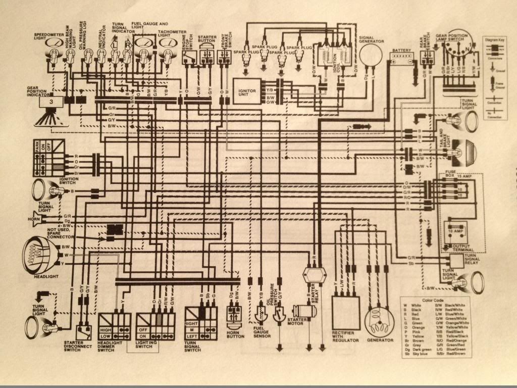
    Ok, so I'm on the final stage of my build and only have the wire harness to go. I've been studying the schematic, but I'm still pretty confused with a couple things.

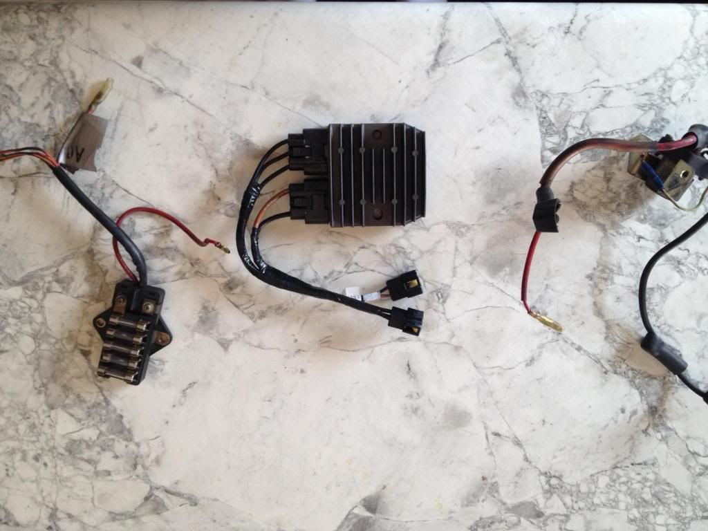
    First, I did buy the Polaris RR with connectors and I want to bypass the headlight bucket route. When you look at the picture the connectors I bought don't match up with anything on the bike so which wires will I cut the connector off of to splice with the stator wires (White w/blue stripe, Yellow, White w/Green stripe)? I think I connect the 3 black wires to the stator, but does it matter which wires they connect to? Also I think out of the 4 other wires (2 black, 2 brown) 1 goes to frame ground, 1 to battery neg, 1 to pos battery and 1 to the pos wire in the harness? I read that I would need a "in-line" fuse to the line going to the battery pos, but I'm not sure what that means? And how do I know which two wires are ground and which are pos?

    Second, Does the black from the solenoid go to the neg on battery and reg go straight to the positive on the battery?

    Third, the fuse box has one thick red wire, one smaller red wire and one plug (Orange w/green strip, Orange w/white, and 2 orange) I'm really confused as to where these wires go as far as the wire harness.

    I'm sorry guys, but I'm reading the threads and schematic, but I want to make sure I don't mess anything up here and I have never done anything electrical like this.

    Thanks,
    Ned

    Last edited by Guest; 04-09-2014, 02:17 PM.

    #2
    Are you looking at color wiring diagram? If not, look at this one from 80 850- should be real similar and easier to follow than black and white one.


    Basically, the red wire feeds fusebox from positive battery terminal (probably a bullet connector setup)-
    You want to send the stator outputs direct to R/R ( do not send one into harness). The R/R positive output should go into harness just like the old R/R; otherwise send it to battery positive using a 20 amp inline fuse.

    It's hard to explain this simply.
    1981 gs650L

    "We are all born ignorant, but you have to work hard to stay stupid" Ben Franklin

    Comment


      #3
      I'm going to sound like an idiot, but is the in-line fuse some type of fuse holder wired to the hot before going to the positive battery? I've never seen an in-line fuse before.

      So the other connector that comes from the RR has two wires that are split to 4 total. One set are brown and one set are black. I assume the brown is really red for positive?
      Last edited by Guest; 04-09-2014, 06:44 PM.

      Comment


        #4
        This should give you a good visual. One side to battery + and the other to R/R +. Hover over the picture for close details. http://shop.advanceautoparts.com/p/b...ne+fuse+holder
        http://www.thegsresources.com/_forum...ine=1440711157'78 GS1000E, Dyna-S ignition, Dyna Green Coils, K&N pods, Delkevic SS 4-1 exhaust, Dynojet Stage 3 jet kit, Russell SS Brake Lines, Progressive suspension, Compu-Fire series Regulator 55402 and Advmonster cree LED headlight conversion.

        Comment


          #5
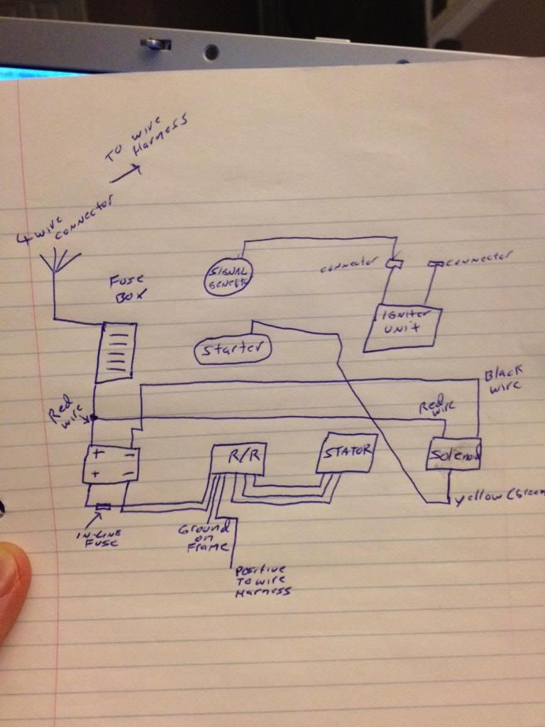
          Ok, so the schematic is very helpful, but some of the colors are not matching up so I assume mine is just a little different because overall its the same. I "think" I have a better idea now. Can you look at my very crude picture and tell me what I'm missing. Not sure about where the other connector from the igniter goes. I'm pretty sure one of the connectors goes to the signal generator.

          Comment


            #6
            Bravo for doing a schematic

            Comment


              #7
              Originally posted by posplayr View Post
              Bravo for doing a schematic
              Yes, "Bravo", but there are some mistakes.

              The starter solenoid is fed directly from the battery + terminal with a LARGE wire. Most of them are black, but somebody might have changed that to a red. That's OK, electrons are color-blind and it's dark inside the insulation, so they can't see, anyway. That LARGE wire will obviously connect to one of the LARGE terminals on the solenoid. Connect the other LARGE terminal of the solenoid to the LARGE terminal on the starter, NOT to the battery -. If you connect it the way you have in your diagram and hit the starter button, there WILL be fireworks.

              The yellow/green wire on the solenoid connects to a similar wire in the harness that comes from the starter button, via the clutch "safety" switch. It does not go to the starter. That "safety" switch can be bypassed inside the headlight bucket, if you wish.

              .
              sigpic
              mine: 2000 Honda GoldWing GL1500SE and 1980 GS850G'K' "Junior"
              hers: 1982 GS850GL - "Angel" and 1969 Suzuki T250 Scrambler
              #1 son: 1986 Yamaha Venture Royale 1300 and 1982 GS650GL "Rat Bagger"
              #2 son: 1980 GS1000G
              Family Portrait
              Siblings and Spouses
              Mom's first ride
              Want a copy of my valve adjust spreadsheet for your 2-valve per cylinder engine? Send me an e-mail request (not a PM)
              (Click on my username in the upper-left corner for e-mail info.)

              Comment


                #8
                Originally posted by Steve View Post
                Yes, "Bravo", but there are some mistakes.

                The starter solenoid is fed directly from the battery + terminal with a LARGE wire. Most of them are black, but somebody might have changed that to a red. That's OK, electrons are color-blind and it's dark inside the insulation, so they can't see, anyway. That LARGE wire will obviously connect to one of the LARGE terminals on the solenoid. Connect the other LARGE terminal of the solenoid to the LARGE terminal on the starter, NOT to the battery -. If you connect it the way you have in your diagram and hit the starter button, there WILL be fireworks.

                The yellow/green wire on the solenoid connects to a similar wire in the harness that comes from the starter button, via the clutch "safety" switch. It does not go to the starter. That "safety" switch can be bypassed inside the headlight bucket, if you wish.

                .
                Steve that is the reason for having a schematic. Duh.

                Comment


                  #9
                  I really am trying to look at the 80 GS850GT schematic and I've made sense of the easy stuff as far as the front end and rear, but I just want to be 100% sure when I connect everything else.
                  Ok, to clarify. I have a red thick wire and black thick wire attached to the starter relay (solenoid) now. I connect the red to the positive terminal, and the black thick wire from the relay directly to the starter? There is also a red wire bullet connector attached to the thick red wire. I'm not sure what that connects to since the schematic only shows two thick wires and the yellow/green. Does it matter if red or black goes to the battery or starter? Since the schematic shows two blacks, like you said about the color of the wire shouldn't matter.

                  Thanks for the help and sorry for not knowing much here.

                  Last edited by Guest; 04-10-2014, 07:40 AM.

                  Comment


                    #10
                    Note on that 850 schematic that on positive battery terminal there is a black (biggie) that runs over to starter solenoid PLUS a red wire (shown big but it's small) that connects to fusebox (this powers fusebox)
                    1981 gs650L

                    "We are all born ignorant, but you have to work hard to stay stupid" Ben Franklin

                    Comment


                      #11
                      I'm looking at the Clymer schematic and it does show a 2nd red wire coming from the relay to the fuse box, not a second wire coming from the battery. So it seems the difference is the 850 schematic shows the battery directly to the fuse box and the 750 schematic shows a red from the battery going into the relay, then coming out and to the fuse box if I'm looking at this correct

                      Last edited by Guest; 04-10-2014, 08:59 AM.

                      Comment


                        #12
                        Some bikes had a 4 fuse fusebox and an output terminal gizmo with another fuse. But your pic in first post showed a 5 fuse fusebox,so I'd stick with 850 layout. Basically,you need to send positive power to fusebox so stuff will be powered up when you turn ignition "ON"- otherwise nothing will happen.
                        1981 gs650L

                        "We are all born ignorant, but you have to work hard to stay stupid" Ben Franklin

                        Comment


                          #13
                          I also bought a spade fuse box to replace the glass as soon as I make sure everything is up and running. As long as the amps are the same, does it matter the physical size of the spade fuses? I bought the smaller ones which fit, but looks like would take the slightly larger ones as well.

                          Comment


                            #14
                            Wiring Questions

                            If you go back to your original photo. On the left is your fuse box the red wire with the male plug goes directly into the red female plug on the solenoid. The other red wire with the tape around it the output of the red wire connected to the solenoid through the #2 fuse. The orange wire with the green stripe powers the #3,4,and 5 fuses and the 3 other wires in that group of 4 get their power from there. It is easy to pop off the back of the fuse box or use a multi meter to see what is connected to what.

                            I have the same question on using the Triumph connector on the R/R. What I think I am hearing is to get rid of the 2 into 4 harness and go directly to battery negative with the single black wire and use a fuse to go directly to the battery with the brown wire as positive. My stock R/R grounded to the battery case with a small wire and the positive came from the wire harness. I don't know if you could tap into the stock connection for power or go directly to battery. Feels strange connecting like a 10 gauge wire to an 18 gauge wire.

                            Comment


                              #15
                              Originally posted by TowPilot View Post
                              ..

                              I have the same question on using the Triumph connector on the R/R. What I think I am hearing is to get rid of the 2 into 4 harness and go directly to battery negative with the single black wire and use a fuse to go directly to the battery with the brown wire as positive. My stock R/R grounded to the battery case with a small wire and the positive came from the wire harness. I don't know if you could tap into the stock connection for power or go directly to battery. Feels strange connecting like a 10 gauge wire to an 18 gauge wire.
                              This will work ,but I still think it's better to put R/R positive into harness (where old one went). Make sure R/R negative has good connection to battery negative - either direct or thru some common grounding point on frame.
                              1981 gs650L

                              "We are all born ignorant, but you have to work hard to stay stupid" Ben Franklin

                              Comment

                              Working...
                              X