Announcement

Collapse
No announcement yet.

82 GS550L polaris r/r install

Collapse
X
 
  • Filter
  • Time
  • Show
Clear All
new posts

    82 GS550L polaris r/r install

    So i confirmed that my stator was bad via no ac voltage between one of the pairs of wires. I got a new stator from rmstator and then had the right ac voltage. Still no voltage at the battery so i got a polaris r/r unit and spliced it in. First test showed about 13-13.5v, which is not quite the 14-15v that should be around 4-5,000rpm.

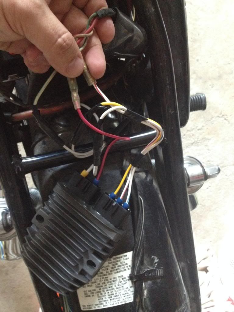
    On the stock wiring one of the stator legs follows the red wire into the harness and then then comes out as another wire and then goes to the r/r.

    Should i wire it so that the 3 stator wires go directly to the r/r or is the stock better?

    #2
    I tried bypassing the wire that goes into the harness and got about the same results.

    With the red wire to the positive on the r/r, negative of the r/r direct to the battery negative, and the 3 stator wires right to the r/r. With the bike not fully warmed up i get 12.5v at 1000rpm and close to 13 at 4-5,000 rpm.

    I rechecked the ac voltage across the stator and that is all good, 22v at 1000 rpm and 60-80v around 5,000rpm.

    Am i missing something? Is my new r/r bad?

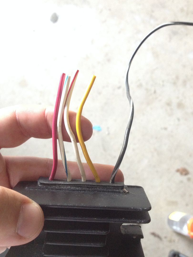
    Pic attached is the old stock r/r

    Comment


      #3
      Read GS Charging Health (in my signature), and it looks like you have too many crimped connections.

      Comment


        #4
        I will try direct wiring the r/r to the battery (with a fuse) tomorrow and eliminate all the old plug connections.

        Comment


          #5
          Stator wires directly into the R/R are a must. Ground to a solid frame point or the battery post. Positive out can go to the battery direct to test voltage. After you get a baseline, reconnect into the harness red wire and see if there is any difference. If going through the harness produces less charging voltage you have losses in the harness and need to clean the connectors.

          Good luck
          Last edited by Nessism; 06-19-2014, 10:28 PM.
          Ed

          To measure is to know.

          Mikuni O-ring Kits For Sale...https://www.thegsresources.com/_foru...ts#post1703182

          Top Newbie Mistakes thread...http://www.thegsresources.com/_forum...d.php?t=171846

          Carb rebuild tutorial...https://gsarchive.bwringer.com/mtsac...d_Tutorial.pdf

          KZ750E Rebuild Thread...http://www.thegsresources.com/_forum...0-Resurrection

          Comment


            #6
            Direct wiring to the battery is not the best idea. You need to use the original Suzuki R/R feed, that is something Suzuki got right. I believe posplayr was referring to your connections to your SH-775. Unless you used a ratchet crimping tool designed for the plastic coated connectors to your R/R, you probably have bad connections there. Common hinged crimping tools are useless garbage. The stator loop through the headlight switch should be abandoned and that stator wire wired directly to the R/R. I hope you cleaned up the rest of your harness, switches, plugs, grounds and fuse box before this because something does not add up unless you got a bad stator. The wiring is simple, three stator wires directly to the R/R, use the Suzuki R/R feed and run the R/R ground directly to the battery negative. You also need to run an additional heavier ground to the R/R mounting plate or bolt, that is something Suzuki got wrong.
            http://www.thegsresources.com/_forum...ine=1440711157'78 GS1000E, Dyna-S ignition, Dyna Green Coils, K&N pods, Delkevic SS 4-1 exhaust, Dynojet Stage 3 jet kit, Russell SS Brake Lines, Progressive suspension, Compu-Fire series Regulator 55402 and Advmonster cree LED headlight conversion.

            Comment


              #7
              So I did a test with the R/R directly and I can now get in the high 13v and it will climb to 14v after about 20-30 seconds at 4,000rpm.

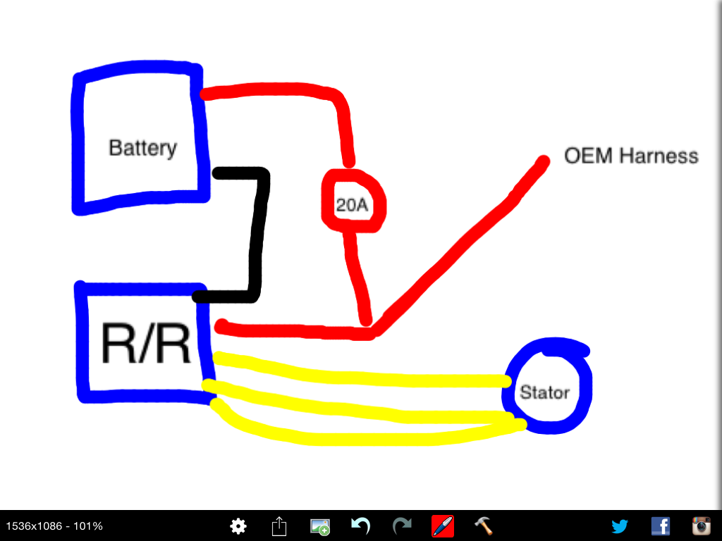
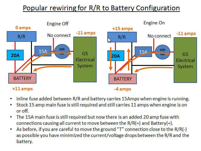
              I am inclined to do my final wiring like my attached sketch based on the diagram. Anyone have any reason not to wire it this way?

              What does the "no connect" mean? Do I need to disconnect a part of the OEM wiring?


              Comment


                #8
                "....it will climb to 14v after about 20-30 seconds at 4,000rpm"

                There's something amiss! my SH-775 hits 14 volts in less than 5 seconds at 2 to 3k rpm from cold start. You got connection problems. It's risky putting a 20 amp fuse as in your sketch- possibility of harness being "fed" with both a 20 amp and 15 amp fuse during a short.
                1981 gs650L

                "We are all born ignorant, but you have to work hard to stay stupid" Ben Franklin

                Comment


                  #9
                  Originally posted by tom203 View Post
                  "....it will climb to 14v after about 20-30 seconds at 4,000rpm"

                  There's something amiss! my SH-775 hits 14 volts in less than 5 seconds at 2 to 3k rpm from cold start. You got connection problems. It's risky putting a 20 amp fuse as in your sketch- possibility of harness being "fed" with both a 20 amp and 15 amp fuse during a short.
                  Gee I wish we had some Quick Test results to review.......................

                  Comment


                    #10
                    Originally posted by snojobz View Post
                    So I did a test with the R/R directly and I can now get in the high 13v and it will climb to 14v after about 20-30 seconds at 4,000rpm.

                    I am inclined to do my final wiring like my attached sketch based on the diagram. Anyone have any reason not to wire it this way?

                    What does the "no connect" mean? Do I need to disconnect a part of the OEM wiring?


                    The "no connect" is that floating wire you show.

                    You can make this work without going direct to the battery and using the larger 20 amp fuse. Just have to chase down the dirt connections between the battery and the R/R (both plus and minus).

                    Start with your fuse box and fuses then the grounds.

                    You will now when you are done when the Revised Phase A voltage drops are good (0.1-0.2V total). The 0.2V per side specified in the test is more of a service limit.

                    Comment


                      #11
                      The connection points that I can find look pretty good, no visible corrosion. I added a bit of dielectric grease to the connections. I now have a loss of about 0.2-0.3v.

                      If I swap my 20amp fuse for a 15 is that not recommended either?

                      Once I figure out which way I am going to wire it I am going to make the connections with the triumph wire harness...

                      Comment


                        #12
                        What is meant by "no connect"? Im guessing it doesn't actually mean dont connect as a fuse wire going to nowhere would be pointless... Let me know. Thanks.

                        Comment


                          #13
                          Bump on this as I just received a SH-775 and have need to know if the connection with the 20 amp fuse is recommended to battery hot.
                          I would like to get the wiring sorted for future stator purchase.

                          STEP
                          1 Three wires from stator wires directly to RR
                          2 Cap w/r and w/g as no longer needed. (white red white green)
                          3 RR hot to main feed as originally wired.
                          4 RR hot to battery positive with 20 amp fuse installed in line.
                          5 RR ground to battery negative terminal.
                          6 RR ground to good frame ground.

                          Comment


                            #14
                            Do step 3 and skip 4. See this

                            1981 gs650L

                            "We are all born ignorant, but you have to work hard to stay stupid" Ben Franklin

                            Comment


                              #15
                              Thank you for the right way and the correct link Tom.
                              I as many others get confused when it comes to this.
                              When I am done soldering I will snap a few pictures, check if I have it correct with a new thread, and if correct I think with the photos as opposed to the diagram there should be less confusion for all.

                              Comment

                              Working...
                              X