Announcement

Collapse
No announcement yet.

Starting from scratch - to relay or not to relay?

Collapse
X
 
  • Filter
  • Time
  • Show
Clear All
new posts

    Starting from scratch - to relay or not to relay?

    I'm finally getting back to my bike build after over 2 years of doing nothing. I'm to the point where I'm wiring the bike up from scratch, eliminating most circuits for now just to get the bike running, and then will add in minor stuff like neutral light, oil temp, etc.

    I'm planning on going with some K&S left and right controls which are cheap and cannot handle many amps (according to reviewers). I'm debating what all circuits I should switch with a relay.

    1. Main relay. I'm going to be doing an RFID ignition, which will switch on a 60 amp relay to enable power to the fuse box where everything will be run from.
    2. Kill switch/ignition relay. Should I utilize a relay for the ignitor / starter solenoid circuit? I'm not sure how many amps run through the ignitor, but even the starter solenoid should pull over 3 amps (4 ohm solenoid). The power for the starter solenoid will run through the kill switch and the starter button, although I could separate those out (allow cranking without spark).
    3. Headlight. Now I certainly want a relay for this, but if it's just one relay then the full amperage would be going through the hi/low switch (what's the point then?). So I assume I'll want one relay for hi and one for low, and both of them SPDT normally closed so the headlight can be disabled during cranking?
    4. Signals. They will be LED so I'm not concerned about that.
    5. Horn, if I add one. I'll want to relay this too.

    Ugh, this is a lot of relaying going on. Am I way off on this? I've looked at the SSPB (which looks awesome), but honestly I'd want more switched circuits.

    Here's where all of this needs to be crammed in

    Attached Files
    1983 GS650G
    Build thread: http://www.dotheton.com/forum/index.php?topic=66251.0

    #2
    Why do you feel you need so many relays? Stock ignition circuit draws about 4 amps (plus 3 more when solenoid is in use)' headlight maybe 5 amps . The 60 amp relay will get bored.

    has this thing run with that airfilter setup? Did you get this critter in pieces, so you decided to get creative?
    1981 gs650L

    "We are all born ignorant, but you have to work hard to stay stupid" Ben Franklin

    Comment


      #3
      I guess I thought I needed the relays just to cut down on the chance of blowing a switch, especially if I use cheap aftermarket ones. Originally I wanted really slim switches mounted on the bars, but I haven't seen anything good that's economical.

      No, it has not run yet with that airfilter, or since I did a complete carb rebuild. I need to get the wiring done first

      I bought it in a semi-running state. The plan was always to strip it down and build it back up.
      1983 GS650G
      Build thread: http://www.dotheton.com/forum/index.php?topic=66251.0

      Comment


        #4
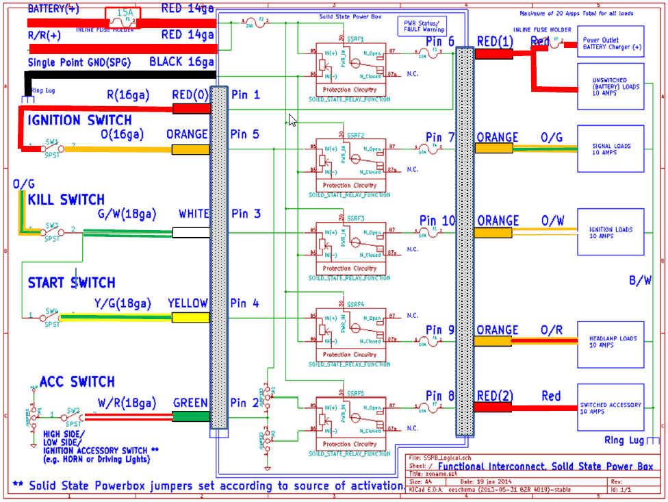
        The SSPB has all the stock circuits plus an additional one (SIGNAL,HEADLAMP,IGNITION,ACC and additionally a switched ACC). There should really be not much need for more. Your total stock loads are only 10 amps and each SSPB channel can do 10 amps. The SSPB is designed as a fusebox replacement and has a very low draw. If you feel you need more channels you can add something like this to a switched output . The PDM60 has a high 50 mAmp current draw so you can't really leave that sitting for weeks on end without draining your battery.

        Comment


          #5
          I think it depends on the general condition of your harness and the switches. If I can get back to about a half a volt, no load, drop by cleaning switches and connections, I'm happy.
          If I was to relay anything it would be coils and headlight.
          97 R1100R
          Previous
          80 GS850G, 79 Z400B, 85 R100RT, 80 Z650D, 76 CB200

          Comment


            #6
            Originally posted by JonnyC View Post
            I'm finally getting back to my bike build after over 2 years of doing nothing. I'm to the point where I'm wiring the bike up from scratch, eliminating most circuits for now just to get the bike running, and then will add in minor stuff like neutral light, oil temp, etc.

            I'm planning on going with some K&S left and right controls which are cheap and cannot handle many amps (according to reviewers). I'm debating what all circuits I should switch with a relay.

            1. Main relay. I'm going to be doing an RFID ignition, which will switch on a 60 amp relay to enable power to the fuse box where everything will be run from.
            This alone will largely remove a major achilles heel. Your ignition switch should no longer be carrying any current.

            2. Kill switch/ignition relay. Should I utilize a relay for the ignitor / starter solenoid circuit? I'm not sure how many amps run through the ignitor, but even the starter solenoid should pull over 3 amps (4 ohm solenoid). The power for the starter solenoid will run through the kill switch and the starter button, although I could separate those out (allow cranking without spark).
            If you keep your fusebox clean then you might get away with just the main real. The ignitor will sink about 3 amps (both coils) The starter solenoid only draws about 150 mAmps; no real concern there and it is not sensitive to low voltage.

            3. Headlight. Now I certainly want a relay for this, but if it's just one relay then the full amperage would be going through the hi/low switch (what's the point then?). So I assume I'll want one relay for hi and one for low, and both of them SPDT normally closed so the headlight can be disabled during cranking?
            Honestly if you get LED lighting the current will drop by at least 1/2 from 5.5 amps for standard H4 Halogen. At 2.5 amps max your headlamp switch should be find. What you would probably like to do is a headlamp cutout using the headlamp relay. I have posted about this.


            4. Signals. They will be LED so I'm not concerned about that.
            You better get a series R/R else you will burn up your stator will all these LED conversions.

            5. Horn, if I add one. I'll want to relay this too.
            You will need one, The SSPB could handle that except if you go to the WOLO which draws 15-30 amps in which case you would need a mechanical relay.

            Ugh, this is a lot of relaying going on. Am I way off on this? I've looked at the SSPB (which looks awesome), but honestly I'd want more switched circuits.
            Not sure what for?

            Here's where all of this needs to be crammed in

            See comments to your "quoted" questions.
            Last edited by posplayr; 06-01-2015, 05:27 PM.

            Comment


              #7
              Ah ok, I was looking at this diagram wrong then...


              For some reason I was looking at the "Signal Loads" (Pin 7) as for the turn signals, not as the (+) source for the rest of the SSPB inputs.

              So I can have the ignition go through the SSPB to power up the kill switch and starter switch, then have those wires lead back into the SSPB to power the ignitor when the run/kill switch is connected and shut the headlight off when cranking. I can then use the aux output for the horn. Pin 7 can also be used then to power the turn/brake, indicator lights, gauges, etc. Now I get it.

              One thing I'm confused by with the diagram. It looks as though the headlight circuit would always be powered on, since it's a n.c. circuit and it's power comes from the battery connection. I assume there's more logic to it than is displayed? And the original source of my confusion is that I expected SSRs 3, 4, and 5 to obtain their power from the output of SSR 2. What I didn't realize was SSR 2 is just used to control the source of the INPUT signal to the following SSRs.

              Side note - that PDM60 looked nice at first, but it's really (for my purpose) a variable amperage fuse box with only two signal sources (IGN and a ground).

              EDIT: Oh, and I do have a FH009AA R/R mounted underneath the electronics tray.
              Last edited by JonnyC; 06-01-2015, 05:35 PM.
              1983 GS650G
              Build thread: http://www.dotheton.com/forum/index.php?topic=66251.0

              Comment


                #8
                Originally posted by JonnyC View Post
                Ah ok, I was looking at this diagram wrong then...


                For some reason I was looking at the "Signal Loads" (Pin 7) as for the turn signals, not as the (+) source for the rest of the SSPB inputs.
                Pin 7 is the power to the entire SIGNAL circuit.
                Pin 6 is unswitched power so it was used to power the ignition switch as Pin 1 and Pin 6 are the same (gotta come from from somewhere it might as well be safe)

                So I can have the ignition go through the SSPB to power up the kill switch and starter switch, then have those wires lead back into the SSPB to power the ignitor when the run/kill switch is connected and shut the headlight off when cranking. I can then use the aux output for the horn. Pin 7 can also be used then to power the turn/brake, indicator lights, gauges, etc. Now I get it.
                Not sure I follow your words (when you say ignition you need to be more clear) I but I get the feeling you understand.

                Generally unswitched power from Pin 1 goes to power the Ignition switch on OEM Red in the stock harness. And the OEM Orange that returns comes right to Pin 5. Pin 6 is also unswitched as pins 1 and 6 are tied internally together so Red(0) and Red(1) are essentially one and the same. When the ignition switch is activated, Pin 5 goes high and the SIGNAL circuit OEM O/G on Pin 7 is activated.

                O/G is used to power the kill switch and the start button same as any Coil relay mod would (take your pick of methods but I have shown my preference)


                One thing I'm confused by with the diagram. It looks as though the headlight circuit would always be powered on, since it's a n.c. circuit and it's power comes from the battery connection. I assume there's more logic to it than is displayed? And the original source of my confusion is that I expected SSRs 3, 4, and 5 to obtain their power from the output of SSR 2. What I didn't realize was SSR 2 is just used to control the source of the INPUT signal to the following SSRs.
                You are correct, that diagram is not drawn correctly. Good job you are the first one to notice that. Unless pin5 is active none of the lower relays (3-5) are active, so in effect to make the diagram correct the second SSR would need to power the following SSR3-5. SSR1 is always on if it is powered so it is a safe source of unswitched power.

                Side note - that PDM60 looked nice at first, but it's really (for my purpose) a variable amperage fuse box with only two signal sources (IGN and a ground).
                You saw the video where I repeatedly grounded a power output and the alternatively powered a light. With the PDM60 you would need to cycle power after each shorting even. There are many more differences; the SSPB is designed for modern load dump environments (+/- 100V) and the drain is much lower. The SSPB has no microcontroller, but rather dedicated safety logic.

                EDIT: Oh, and I do have a FH009AA R/R mounted underneath the electronics tray.


                You want to get rid of the FH009AA (it is MOSFET but still SHUNT)it will fry your stator. The SH-775 is probably the same form factor and should fit right in.

                Comment


                  #9
                  Ugh. So the FH009 is completely different than the FH012 then? Seems there were some people using the 009, and a lot using the 012. Honestly there's way too much confusing stuff on this site now regarded R/R's.
                  1983 GS650G
                  Build thread: http://www.dotheton.com/forum/index.php?topic=66251.0

                  Comment


                    #10
                    Originally posted by JonnyC View Post
                    Ugh. So the FH009 is completely different than the FH012 then? Seems there were some people using the 009, and a lot using the 012. Honestly there's way too much confusing stuff on this site now regarded R/R's.
                    FH009 and FH012 are all SHUNT R/Rs. Read GS Stator in my signature; there are only a handful of SERIES R/R's.

                    Comment


                      #11
                      Originally posted by posplayr View Post
                      FH009 and FH012 are all SHUNT R/Rs. Read GS Stator in my signature; there are only a handful of SERIES R/R's.
                      Thanks, I just spent a bunch of time reading up on here and elsewhere. Thanks for all of the info! All of the previous shunt R/R info should be deleted and replaced with the SH-775, and the R/R list page should just redirect to your GS Stator page

                      So PowerSportsNation on Ebay has a TON of SH775's for $50, so I think I'll go with one of those - http://stores.ebay.com/powersportsna...1&_nkw=4012941
                      1983 GS650G
                      Build thread: http://www.dotheton.com/forum/index.php?topic=66251.0

                      Comment


                        #12
                        Originally posted by JonnyC View Post
                        Thanks, I just spent a bunch of time reading up on here and elsewhere. Thanks for all of the info! All of the previous shunt R/R info should be deleted and replaced with the SH-775, and the R/R list page should just redirect to your GS Stator page

                        So PowerSportsNation on Ebay has a TON of SH775's for $50, so I think I'll go with one of those - http://stores.ebay.com/powersportsna...1&_nkw=4012941
                        There was a recent update.

                        Comment

                        Working...
                        X