I'm kidding! I've been perusing the forum over the last couple weeks, and I've read enough to know that is arguably a "stupid question", given the number of times it has been covered.
But I did buy a 1979 GS 850, and it does have a known charging problem. The PO was probably the nicest seller I've ever met through c'list. He spent some time going through the issues with the bike (and there are a number of them
 ), explaining the parts he's replaced, etc etc. He threw in all the OEM parts he replaced, a Clymer manual, some spare spark plugs and whatnot. He also kept pretty good records of what he has fixed in the manual. So a quick shout out to Steve in Philippi, WV!
Anyway, I've been working my way through the Stator Papers, and I need some guidance in a few areas...
Phase A
Step #1
The battery is brand new, but I've been running the bike some over the past few weeks, maybe 30 minutes total. I ran through the "quick test" procedures yesterday, just to get a good idea of where the battery is at:
- When just turning the key to "on" so the lights are on for 10 seconds or so, the battery is at 11.92v. (The headlight is not installed, so only the tail/brake light was actually on during this time.)
- After the bike has warmed up for a few minutes and is idling (choke down), the battery is at 12.4v.
- At 2500rpm the battery is at 13.02v.
- At 5000rpm the battery drops slightly to 12.88v.
Step #2
When running @ 5000rpm with the black lead on battery (+), and red lead on red output of R/R, reading was 0.63v.
The SP calls for "checking the entire lead". So that would mean checking from the battery to the fuse box (the Main fuse), from the red wire out of the fuse box to the 'T' where it connects with the red wire out of the R/R and the red from the ignition switch. According to the wiring diagram, the red output from R/R connects up with a red lead from the fuse box. I read somewhere on here that the 'T' connection happens above the air box, behind the fuel control switch.
How often is that 'T' connection a source of the problem? I would probably have to remove the gas tank to check it, so unless it is something that is often an issue, I'd rather avoid messing with the tank.
When it comes to the fuse box, what would I be looking for? I pulled that back of the box off, and all the soldering looks OK. The bike has 30k miles on it, but it was garage kept, so there isn't a lot of gunk on the connectors. Is using the multimeter to check resistance along the wiring something that makes sense?
Next time I am at my storage unit, I'll try to take a few pics of the connectors and fuses.
Step #3
When running @ 5000rpm with the red lead on the battery (-), and the black lead on the black/white output of R/R, the reading was 0.96v.
That was around 2 weeks ago. I noticed that the black/white ground out of the R/R had a 1/2" section where the plastic was stripped back. I think the PO might have used this point to do this test voltage - at least that is what I used it for.
I went ahead and routed the ground straight to the battery (-), as suggested in the SP.
Retesting, the reading dropped to 0.05v, which is pretty good.
But to get that reading, I had the red lead on the battery (-), and the black lead an inch away on the crimped fork connector. How else would I test Step #3 with the R/R grounded straight to the battery?
Phase B
Step #1
The only consistent readings I was able to get are below:
Yellow & blue/white 3.5ohm
Blue/white & green/white 4.0ohm
Green/white & yellow 4.5ohm
Could this be the result of slightly corroded connectors? The green/white connector had some greenish corrosion it, but it just looked like surface patination. Again, I'll try to post some more pictures over the next couple days.
I will probably continue with the rest of the testing this weekend, unless y'all think that the stator is toast.
Quick side question:
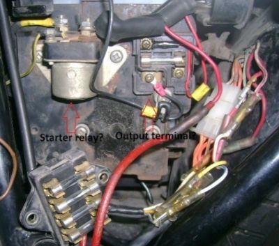
Am I correct in thinking that in the picture below those two widgets are the starter relay and the output terminal?

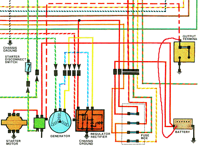
What does the output terminal do? Is it correct that it just has one wire going straight to the (-) battery terminal, and one straight the to (+)? I ask because the wiring diagram for the bike has the (+) wire (from the Output Terminal) going to the starter relay (or to what I am assuming is the starter relay). Now technically the red (+) on the output terminal does connect to the red (+) on the starter relay, but it happens at the (+) battery terminal.
On the wiring diagram below, I partially erased the red (+) wire from the output terminal to the starter relay, and drew the wire going straight from the Output Terminal to battery. This is how my bike is currently wired:

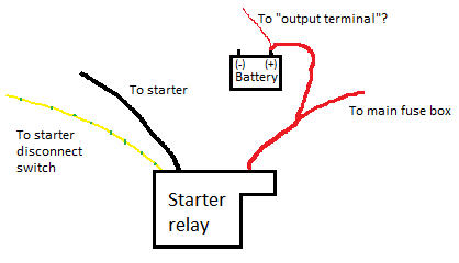
My Starter Relay only has 3 wires connected to it; compared to the diagram above it is missing the red wire to the Output Terminal and the ground. Below is the current wiring.

Sorry for the mega-post full of questions, I just wanted to lay everything as I currently understand it out on the table.
I appreciate any answers, critiques, or suggestions!
.png)
.png)

Comment