Announcement

Collapse
No announcement yet.

Trail Tech Vapor Tach Problems

Collapse
X
 
  • Filter
  • Time
  • Show
Clear All
new posts

    Trail Tech Vapor Tach Problems

    Today I did a test run with a Vapor on my 82 1100E. I hooked up the tach and head temperature sensor to see if they would work or if the tach would suffer from bounce due to ignition noise. It did. The bar graph read out wasn't too bad and I could probably live with it as is, but the digital RPM display showed the reading bouncing all over the place through a 1000+RPM range. It never seemed to read lower than the Suzuki tach, but was continually bouncing higher. The manual says the bounce should be less than +/-100rpm, so this is not at all correct.

    I used the inductive lead wrapped around the plug wire for the signal and went from 7 wraps starting down to 1.5 wraps with no change in the bounce. The black wire on the lead was grounded to a bare spot on the frame so it should have been solid enough to work correctly.

    I know some people here have used the Vapor with success and am hoping I can get some tips on how to sort this so I can dump my flaky stock dash and clean up the front end. All experiences/tips/thoughts welcome.


    Thanks,
    Mark
    1982 GS1100E
    1998 ZX-6R
    2005 KTM 450EXC

    #2
    Can you change the amount of ignition pulses it picks up on in the Trail Tech? As in change it from 4-stroke to 2-stroke? A 4-stroke with the wasted spark method will give it a reading twice the speed it's actually running (compared to if it was fitted to a DRZ400 for instance).
    1996 GSF1200 — Pretty Much Standard.
    1983 GSX750ES — Cafe Racer Project
    1980 GS550E — 673 Conversion.
    1980 GS400 — Cafe Racer???

    http://biketech7.blogspot.com.au

    Comment


      #3
      Originally posted by Chancho196 View Post
      Can you change the amount of ignition pulses it picks up on in the Trail Tech? As in change it from 4-stroke to 2-stroke? A 4-stroke with the wasted spark method will give it a reading twice the speed it's actually running (compared to if it was fitted to a DRZ400 for instance).
      It has the correct setting for pulses, the problem is ignition noise making the readout jump around.


      Mark
      1982 GS1100E
      1998 ZX-6R
      2005 KTM 450EXC

      Comment


        #4
        I had the same issue. I actually can't recall if I fixed it last year. Bike has been down and out for some work since I added the resistor.

        I just have a followup question. I wrapped the provided tach wire around a plug wire, but no matter how many wraps I used it was quite unreliable. It even registered with the wire not wrapped at all, quite a few inches away from any plug wires. I ended up just hooking it up to the negative low-voltage side of my coil, and it's better, but it still jumps around quite a bit (like 400 rpm swing when holding the throttle steady).
        What can I do? Is there an alternate cable I can buy to hook it up to the low side coil, because I know the single wire cable provided is meant for the wrap method.
        The next thing to do would be to install an inline resistor in the sensor lead. We recommend using a 600k ohm ¼ watt resistor.
        1983 GS650G
        Build thread: http://www.dotheton.com/forum/index.php?topic=66251.0

        Comment


          #5
          I don't know if anybody cares or not, but I got it sorted after contacting the dealer who sold it to me a number of years ago. I hooked the signal wire up to one of the coil primaries, cleaned up the excess signal wire dangling around and installed resistor spark plugs. All of this got the bounce down to +/-50rpm or so, which is more than adequate for my uses. The Vapor now shows that the OEM Suzuki tach is running worse than I thought, reading low at higher RPM and drifting high when dropping to idle from higher RPM. I have some on-road testing to do before I am 100% satisfied, but everything seems to be working as expected now.


          Mark
          1982 GS1100E
          1998 ZX-6R
          2005 KTM 450EXC

          Comment


            #6
            Originally posted by mmattockx View Post
            I don't know if anybody cares or not, but I got it sorted after contacting the dealer who sold it to me a number of years ago. I hooked the signal wire up to one of the coil primaries, cleaned up the excess signal wire dangling around and installed resistor spark plugs. All of this got the bounce down to +/-50rpm or so, which is more than adequate for my uses. The Vapor now shows that the OEM Suzuki tach is running worse than I thought, reading low at higher RPM and drifting high when dropping to idle from higher RPM. I have some on-road testing to do before I am 100% satisfied, but everything seems to be working as expected now.


            Mark
            I think I recall someone else having similar problems with RPM hook up, but sounds like a good solution. The other potential location might be the Ignitor pickup and might be even quieter.

            Comment


              #7
              I've ran the vapors on ATVs and they are remarkably durable and easy to use. I never had much luck using the wire wrapped around the plug wire lead. On the two at home, they are wired to the coil lead and work great.
              1982 GS1100E "Jolene"

              Comment


                #8
                Bumping this back up. I'm having a hell of a time getting a good signal to my Trail Tech Vapor. I've tried multiple configurations, but right now i'm just trying to figure out how to get a reliable signal from the ground terminal of the primary coil. I have a Dyna S with Dyna 3 ohm coils, copper core wires with resistor plug caps. No matter what I do I seem to be getting random feedback from the other coil so my tach is constantly bouncing around.

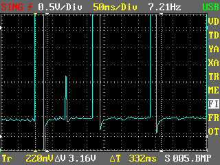
                I broke out my inexpensive DSO Nano oscilloscope to see what is going on. Here's a measurement from the negative connection on the coil...


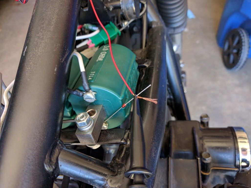
                Here I tried to connect a 12.1v zener diode, reverse biased on the coil (band on the coil connection side).


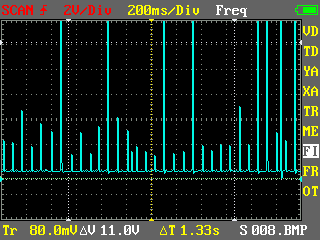
                I was hoping any minor voltage spikes (below 12v) would get filtered out. Here is a view over a longer duration...


                You can see that there are still spikes from what seems like the other coil, and I'm surprised to see that the voltage is not consistent (this is with an idling bike). I assume the spike is either due to inductance noise or fly-back voltage from the coil making it's way through to the other coil's terminal?

                I have a optocoupler on the way that I was going to try out (diagram here), but it seems that might have the same problem. One other option might be just to hook the tach signal wire up to both coils with diodes, then I will change the tach settings on the Trail Tech. I'm not sure how accurate this would be though in higher RPMs.

                Maybe a fly-back diode connected between the positive and negative coil terminal?

                As you can see, I'm pretty dumb when it comes to electronics, so any advice would be appreciated
                Last edited by JonnyC; 09-20-2016, 03:47 PM.
                1983 GS650G
                Build thread: http://www.dotheton.com/forum/index.php?topic=66251.0

                Comment


                  #9
                  Originally posted by JonnyC View Post
                  Bumping this back up. I'm having a hell of a time getting a good signal to my Trail Tech Vapor. I've tried multiple configurations, but right now i'm just trying to figure out how to get a reliable signal from the ground terminal of the primary coil. I have a Dyna S with Dyna 3 ohm coils, copper core wires with resistor plug caps. No matter what I do I seem to be getting random feedback from the other coil so my tach is constantly bouncing around.

                  I broke out my inexpensive DSO Nano oscilloscope to see what is going on. Here's a measurement from the negative connection on the coil...


                  Here I tried to connect a 12.1v zener diode, reverse biased on the coil (band on the coil connection side). I was hoping any minor voltage spikes (below 12v) would get filtered out. Here is a view over a longer duration...


                  You can see that there are still spikes from what seems like the other coil, and I'm surprised to see that the voltage is not consistent (this is with an idling bike). I assume the spike is either due to inductance noise or fly-back voltage from the coil making it's way through to the other coil's terminal?

                  I have a optocoupler on the way that I was going to try out (diagram here), but it seems that might have the same problem. One other option might be just to hook the tach signal wire up to both coils with diodes, then I will change the tach settings on the Trail Tech. I'm not sure how accurate this would be though in higher RPMs.

                  Maybe a fly-back diode connected between the positive and negative coil terminal?

                  As you can see, I'm pretty dumb when it comes to electronics, so any advice would be appreciated
                  As mentioned earlier in this thread, use the pickup off the crank.

                  Comment


                    #10
                    The Dyna S is all self-contained though, so the only connection is where it connects to the negative terminal on the coil.

                    1983 GS650G
                    Build thread: http://www.dotheton.com/forum/index.php?topic=66251.0

                    Comment


                      #11
                      Fair enough . I can not interpret your scope trace as the volts/div is not obvious. You might try wrapping the sense wire around one of the primary wires. Might have to do 10-20?

                      btw , not sure what that diode is going to do for you? What are you trying to do?limit emf spikes over 12v?
                      Last edited by posplayr; 09-20-2016, 04:09 PM.

                      Comment


                        #12
                        I see now the first plot was 0.5v per division. You need to put the annode to ground if you want to limit the voltage spikes. Not sure how that little Zener is going to hold up. Best to use a resistor and diode from coil(-) to ground the tap off the cathode .

                        Comment


                          #13
                          The scope images are awesome aren't they? The zener diode idea was to put it in series, reverse biased, with the tach pickup wire. In theory (or at least in my ignorant head) it would drop 12.1v off the reading, so it would require a spike of 12.1v or more to make it through to the pickup wire.

                          The sad thing is, even without the pickup wire even connected to the Trail Tech, it still gets an RPM reading.
                          1983 GS650G
                          Build thread: http://www.dotheton.com/forum/index.php?topic=66251.0

                          Comment


                            #14
                            Hopefully you can read this. This will limit the Tach signal to -0.5<TACH<+5V without affecting operation of the Dyna-S
                            Attached Files
                            Last edited by posplayr; 09-20-2016, 04:37 PM.

                            Comment


                              #15
                              JonnyC, Not sure about how to hook up your tach but both pickup coils have two wires. One is red which is the voltage. The other is the signal. It wouldn't be very hard to splice into one of these with a wire to run up to the tach; make sure you cover the wire with heat shrink again after soldering.

                              Comment

                              Working...
                              X