Announcement

Collapse
No announcement yet.

81 750E charging system testing

Collapse
X
 
  • Filter
  • Time
  • Show
Clear All
new posts

    81 750E charging system testing

    Installed a new stator and a new RR recently on a 1981 gs750E. Stator is good, delivering up to 80 volts AC with engine revving.

    However, i'm getting curious readings at the battery terminals, and I'm not sure whether my RR is operating properly. Battery is a new Lithium Phosphate lightweight type battery, which very well could be a variable. Im not sure if the RR's activity changes depending on the load. I've taken 2 videos to show my testing procedures and results.


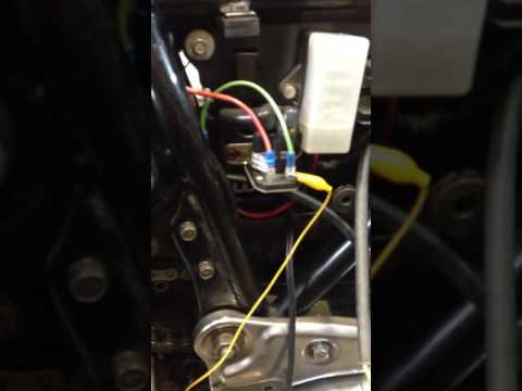
    In the first video, i'm measuring the voltage output from the R/R between the hot and the ground leads. Seems extremely low, never more than 4 volts... curiously, the DC voltage DROPS as engine speed increases. not sure what to make of that. Seems wrong, maybe an electrical engineer can confirm or deny the weirdness.


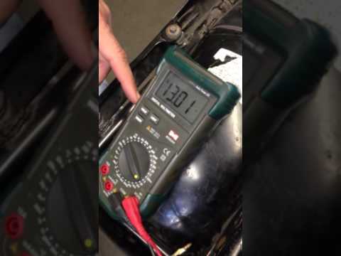
    The second video shows what happens when I'm metering across the battery terminals (via battery tender pigtail). Voltage is strong (13v), but doesn't change significantly with engine speed.


    It's hard to tell what is happening, overall. The RR gets pretty warm to the touch, but not HOT HOT.
    I wonder if the Lithium battery has something to do with it. I will have a chance to put a sealed traditional battery in next week and see if the charging circuit acts differently.
    any thoughts?
    81 gs1100E
    81 gs550
    74 xlch 1000 custom
    03 ktm 525 exc supermoto
    76 honda cj360
    72 honda cl350
    2 green parrots

    #2
    The Quick test would provide a baseline to work from. Also know the exact battery by part number might help.

    No idea what you are measuring in the first video.

    Comment


      #3
      Battery is this one: WPS Featherweight Lithium Battery HJTX14AHL-FP-IL

      https://www.amazon.com/gp/product/B00DX895CA/

      In the first video, i had the stator hooked to the 3 yellow wires on the R/R accepting AC voltage. the negative wire from the R/R was frame grounded. The positive wire from the R/R was connected to the Red probe of my meter. the Black probe was connected to a good ground source. I tested continuity between my ground and the R/R's ground location, so ESSENTIALLY I'm just metering the positive and negative wires from my R/R.
      81 gs1100E
      81 gs550
      74 xlch 1000 custom
      03 ktm 525 exc supermoto
      76 honda cj360
      72 honda cl350
      2 green parrots

      Comment


        #4
        Quick Test Results:

        1.) key off................Normal 12.7 volts-12.9 volts 13.0 v

        2.) key on (but not cranking with lights for 10 sec).....Normal 12.2-12.5 volts 12.7 v

        3.) at idle (1500 rpm).....12.6volts - 13.2volts 13.0v

        4.) at 2500 rpm 13.5 -14.0 volts 13.0v

        5.) at 5000 rpm.....14.0 -15.0 volts 13.0v

        6.) key off.....slightly higher than measurements # 1 (12.8-13.0 v) 13.0v
        81 gs1100E
        81 gs550
        74 xlch 1000 custom
        03 ktm 525 exc supermoto
        76 honda cj360
        72 honda cl350
        2 green parrots

        Comment


          #5
          Originally posted by CincinnatiKid View Post
          Battery is this one: WPS Featherweight Lithium Battery HJTX14AHL-FP-IL


          In the first video, i had the stator hooked to the 3 yellow wires on the R/R accepting AC voltage. the negative wire from the R/R was frame grounded. The positive wire from the R/R was connected to the Red probe of my meter. the Black probe was connected to a good ground source. I tested continuity between my ground and the R/R's ground location, so ESSENTIALLY I'm just metering the positive and negative wires from my R/R.
          What you describe is not clear without a lot of guessing. For example "metering" is not a specific term. It does not specific what you are measuring VDC,VAC,Ohms.

          You would be well to follow establish procedures instead of making this up as you go. See Stator pages for specific tests.


          You should not test a R/R with it disconnected from the battery; it will probably get very hot and tell you nothing and that includes me.

          Comment


            #6
            Originally posted by CincinnatiKid View Post
            Quick Test Results:

            1.) key off................Normal 12.7 volts-12.9 volts 13.0 v

            2.) key on (but not cranking with lights for 10 sec).....Normal 12.2-12.5 volts 12.7 v

            3.) at idle (1500 rpm).....12.6volts - 13.2volts 13.0v

            4.) at 2500 rpm 13.5 -14.0 volts 13.0v

            5.) at 5000 rpm.....14.0 -15.0 volts 13.0v

            6.) key off.....slightly higher than measurements # 1 (12.8-13.0 v) 13.0v
            Thanks much better. I'm not familiar with that battery but I would assume it is intended to be a led acid replacement and should have a similar charging characteristic. That being assumed you are not charging.

            I don't know if you did the Phase B tests. You can ignore the resistance tests as they are meaningless. Do the leg to leg and leg to ground tests at 5K RPM.

            Alternatively you could do the Phase A tests and see if you just have crappy connections. If you see large voltage drops, you are charging just losing it all in the connections.

            The frame is not a good ground. See GS Charging health and look up SPG. Single Point Ground.
            Last edited by posplayr; 10-16-2016, 01:48 PM.

            Comment


              #7
              copy all that, especially the part about a heating up R/R
              ive successfully troubleshot charging issues on bikes before, using the electrosport fault finding diagram. i'll follow your flowchart this week when i get back to the bike and see what I can discover.

              re: metering - i used VAC for stator leg-leg connections (80+VAC @ 5k), and VDC for all voltage measurements downstream of the RR. sorry for the confusion. I made a lot of other tests while shooting those videos... some helpful, some not so helpful. I still have the replaced OEM R/R that I was comparing results against. The OEM one passes the diode test, but allows voltages of 16+ VDC.

              re: SPG - I just read up on it. I'll put some work towards new wiring connections.
              81 gs1100E
              81 gs550
              74 xlch 1000 custom
              03 ktm 525 exc supermoto
              76 honda cj360
              72 honda cl350
              2 green parrots

              Comment


                #8
                Originally posted by CincinnatiKid View Post
                copy all that, especially the part about a heating up R/R
                ive successfully troubleshot charging issues on bikes before, using the electrosport fault finding diagram. i'll follow your flowchart this week when i get back to the bike and see what I can discover.

                I updated the ElectroSport fault finding and most got into the revisions I pointed to. The main objections I had to the update was the continued use of an ohm meter which is a waste of time or worse. It is fine if you ignore whatever you measure. The new stator pages also retain the R/R tests which only apply to the SHUNT R/R which you should ditch.

                re: metering - i used VAC for stator leg-leg connections (80+VAC @ 5k), and VDC for all voltage measurements downstream of the RR. sorry for the confusion. I made a lot of other tests while shooting those videos... some helpful, some not so helpful. I still have the replaced OEM R/R that I was comparing results against. The OEM one passes the diode test, but allows voltages of 16+ VDC.

                The leg to ground are generally better than the leg to leg although you should do both; they test different types of stator shorts.
                Diode test will not tell you if the regulator portion is fired which is sounds like it is. These R/R tests are also meaningless for a SERIES R/R. They simply do not apply
                re: SPG - I just read up on it. I'll put some work towards new wiring connections.
                It really is simple and only adds two wires above how the bike came stock.

                ....................

                Comment


                  #9
                  Originally posted by CincinnatiKid View Post
                  Battery is this one: WPS Featherweight Lithium Battery HJTX14AHL-FP-IL


                  In the first video, i had the stator hooked to the 3 yellow wires on the R/R accepting AC voltage. the negative wire from the R/R was frame grounded. The positive wire from the R/R was connected to the Red probe of my meter. the Black probe was connected to a good ground source. I tested continuity between my ground and the R/R's ground location, so ESSENTIALLY I'm just metering the positive and negative wires from my R/R.
                  It looks like your first vid you have opened the r/r positive connector to measure the voltage to ground. In volt mode your meter is a high impedance and very little current is flowing.
                  That's probably why you are seeing low voltage.
                  I stick a probe up the back of the connectors without opening them to get voltages there.
                  97 R1100R
                  Previous
                  80 GS850G, 79 Z400B, 85 R100RT, 80 Z650D, 76 CB200

                  Comment


                    #10
                    Originally posted by Brendan W View Post
                    It looks like your first vid you have opened the r/r positive connector to measure the voltage to ground. In volt mode your meter is a high impedance and very little current is flowing.
                    That's probably why you are seeing low voltage.
                    I stick a probe up the back of the connectors without opening them to get voltages there.
                    Actually I believe what happens is when the terminals are open circuit, the terminal voltage of the R/R goes above the 14.5V limit so the R/R detects over voltage and starts SHUNTING 100% (chopping). The R/R will get hot (becuase it is shorting the stator )and you probably see an average voltage that is low.

                    Comment


                      #11
                      okay i got it charging. rewired some things, got the SPG goin on, and I can see where all the voltage is now. chopped some of the old connectors and crimped new ones in their place. helped recover some voltage there.

                      here's a basic drawing of where the wiring is at the moment //// pink - hot //// green - negative


                      pretty much what the "preferred schematic" has. It's charging well enough now to keep the battery happy at idle and above. that i am satisfied with.

                      but now I have an issue with the lighting circuit. it's blowing fuses as soon as I turn the headlight on. That's a whole other thing to dig into tomorrow.

                      Most of my Voltage drop (about .4v) is happening in that power send from the R/R to the front of the bike (ignition keyswitch...?) and returning to the fuse box. The issue is that there are 2 separate power inputs for the fuse box. one is a RED wire (for charging circuit to battery) and the other is an ORANGE wire that feeds the ignition, signals, and light circuit in parallel. I'd like to redesign that, but not sure the best way.

                      speaking of ignition keyswitches... i discovered this, i wonder if it's a problem or just a little feature:
                      Attached Files
                      81 gs1100E
                      81 gs550
                      74 xlch 1000 custom
                      03 ktm 525 exc supermoto
                      76 honda cj360
                      72 honda cl350
                      2 green parrots

                      Comment


                        #12
                        Originally posted by CincinnatiKid View Post
                        okay i got it charging. rewired some things, got the SPG goin on, and I can see where all the voltage is now. chopped some of the old connectors and crimped new ones in their place. helped recover some voltage there.

                        here's a basic drawing of where the wiring is at the moment //// pink - hot //// green - negative


                        pretty much what the "preferred schematic" has. It's charging well enough now to keep the battery happy at idle and above. that i am satisfied with.

                        [/video]
                        You are doing some imaginative wiring. You added more than nessesary connections between the R/R(+) and the Battery(+). There should only be a single fuse between them; You put the ignition switch in there are well (bad mistake).
                        0.4V drop is the result and it is at least twice what it should be

                        You also omitted the harness B/W ground from the SPG although that will not affect charging.

                        Put both OEM and you diagram side by side and highlight the part between teh battery and the R/R. You shoudl be able to see the clear difference.
                        Last edited by posplayr; 10-18-2016, 09:59 PM.

                        Comment


                          #13
                          a PO has done some things to this wiring, i'd assume. the OEM wiring guide shows me what ought to be there, but not really what is there.

                          my R/R+ and the fuse panel both have a female Bullet connection on a red wire... they wont join up together.

                          there are 2 red wires with MALE Bullet connections in the wiring harness (to ignition switch i'm assuming... haven't verified). these wires have continuity (about 1 ohm). currently, these two male plugs are in the female connectors from above, and if i disconnect one, the bike won't run.

                          My fuse panel has two separate circuits for power input. a red wire circuit (voltage to battery) and an orange wire circuit (voltage to accessories and ignition and lights). Where should this orange circuit see it's power from? it has to pass through the ignition switch at some point.

                          instead of running another 14awg line from the fuse box direct to the batt+ lug, I connected to the easier and more accessible solenoid terminal. a fat 10 or 8awg wire goes from the solenoid to the battery.

                          back at it in the morning time.
                          81 gs1100E
                          81 gs550
                          74 xlch 1000 custom
                          03 ktm 525 exc supermoto
                          76 honda cj360
                          72 honda cl350
                          2 green parrots

                          Comment

                          Working...
                          X