Announcement

Collapse
No announcement yet.

sh-775 blowing fuse

Collapse
X
 
  • Filter
  • Time
  • Show
Clear All
new posts

    sh-775 blowing fuse

    I've replaced my stator with a caltric stator and my R/R with a SH-775. I'm getting the suggested voltages as recommended in the "Stator Papers" My question is regarding the fuse going from the R/R to the battery on the positive leg. I've used a 15 amp fuse, but it blows when I rev the bike. Are there going to be transients that spike over 15 amps occasionally that will cause a 15 amp fuse to blow? Running a 20 amp fuse it doesn't blow. When riding the new voltmeter that I just installed will show 14.2 volts.

    Any thoughts would be greatly appreciated.

    Thanks
    Smithfield, UT
    1980 GS1000G

    #2
    Originally posted by Chrisf View Post
    I've replaced my stator with a caltric stator and my R/R with a SH-775. I'm getting the suggested voltages as recommended in the "Stator Papers" My question is regarding the fuse going from the R/R to the battery on the positive leg. I've used a 15 amp fuse, but it blows when I rev the bike. Are there going to be transients that spike over 15 amps occasionally that will cause a 15 amp fuse to blow? Running a 20 amp fuse it doesn't blow. When riding the new voltmeter that I just installed will show 14.2 volts.

    Any thoughts would be greatly appreciated.

    Thanks
    This is the downside of how you connected the R/R direct to +BAT instead of through the OEM fuse box. Consider yourself lucky some people have to go to 25 amp fuse.

    I have documented the analysis in GS Charging health.


    If you stock with teh stock configuration you only need a 15 amp fuse.


    Technical Info posts that are deemed to be important or popular will be placed here for easier access. If you feel a post should be moved from the Technical Info forum to here then PM the Administrator with your request.


    I would recommend connecting your R/R as described with a SPG.


    Last edited by posplayr; 12-13-2019, 05:03 PM.

    Comment


      #3
      Thanks posplayr,

      I can go through the fuse box. I have replaced the original fuse box with an Eastern Beaver PC-8. If I run it through the panel, are you saying that the other circuits will pull power as needed before going to the battery?

      I have also created a direct run from the fuse box to the coils, and I'm monitoring voltage with the aforementioned voltage meter off of that circuit.

      When you state SPG, you are meaning a single point of ground, correct? Is it detrimental to have those circuits go directly to the battery, which then goes to the engine case for ground?

      Thanks again for the link. I'm reading through that thread now.
      Last edited by Chrisf; 12-13-2019, 05:31 PM.
      Smithfield, UT
      1980 GS1000G

      Comment


        #4
        Originally posted by Chrisf View Post
        Thanks posplayr,

        I can go through the fuse box. I have replaced the original fuse box with an Eastern Beaver PC-8. If I run it through the panel, are you saying that the other circuits will pull power as needed before going to the battery?

        I have also created a direct run from the fuse box to the coils, and I'm monitoring voltage with the aforementioned voltage meter off of that circuit.

        When you state SPG, you are meaning a single point of ground, correct? Is it detrimental to have those circuits go directly to the battery, which then goes to the engine case for ground?

        Thanks again for the link. I'm reading through that thread now.
        There are different ways to connects a Western Beaver so without a schematic I don't know how to relate that to my analysis.
        The starter ground only dominates when the starter is running. You don't want to rely on that the rest of the time when in charging mode.

        I have some grounding threads where i analyze the groudn return paths and show that he SPG minimized voltage drops on the grounds. If there was nothing cvalled corriosion then it would npot matter, howver when there is corrosion this becomes imporant to keep those drops low .
        See Stator pages measuring Phase A "voltage drops".

        Comment


          #5
          This may help...

          SH775 Install by nessism, on Flickr
          Ed

          To measure is to know.

          Mikuni O-ring Kits For Sale...https://www.thegsresources.com/_foru...ts#post1703182

          Top Newbie Mistakes thread...http://www.thegsresources.com/_forum...d.php?t=171846

          Carb rebuild tutorial...https://gsarchive.bwringer.com/mtsac...d_Tutorial.pdf

          KZ750E Rebuild Thread...http://www.thegsresources.com/_forum...0-Resurrection

          Comment


            #6
            In the stock wiring, the R/R output is fed to the bike between the fusebox and the battery. The bike would take whatever it would need (usually about 10-15 amps), the rest of the output would charge the battery. If I remember correctly, Posplayr posted a chart some time back that showed the maximum output of the charging system was 22-25 amps. That means that the battery charge would be 7-10 amps. If you route ALL of that output to the battery + terminal, you will be feeding the bike AND the battery through that fuse.

            The stock MAIN fuse is 15 amps. When you turn the key ON, all the current the bike is using to power the coils, lights, etc. is flowing through that fuse, but it's less than 15 amps. When you start the bike, the R/R is then feeding the bike and only the excess is flowing backward, into the battery. That 7-10 amp flow is definitely less than the fuse rating, which is why you get by with a 15-amp fuse.

            .
            sigpic
            mine: 2000 Honda GoldWing GL1500SE and 1980 GS850G'K' "Junior"
            hers: 1982 GS850GL - "Angel" and 1969 Suzuki T250 Scrambler
            #1 son: 1986 Yamaha Venture Royale 1300 and 1982 GS650GL "Rat Bagger"
            #2 son: 1980 GS1000G
            Family Portrait
            Siblings and Spouses
            Mom's first ride
            Want a copy of my valve adjust spreadsheet for your 2-valve per cylinder engine? Send me an e-mail request (not a PM)
            (Click on my username in the upper-left corner for e-mail info.)

            Comment


              #7
              Once you realise that it is the generator that runs the bike , not the battery, wiring choices become clearer.
              97 R1100R
              Previous
              80 GS850G, 79 Z400B, 85 R100RT, 80 Z650D, 76 CB200

              Comment


                #8
                Thanks everyone. I'll try and put together a schematic this weekend and post it.
                Smithfield, UT
                1980 GS1000G

                Comment


                  #9
                  Originally posted by Chrisf View Post
                  Thanks everyone. I'll try and put together a schematic this weekend and post it.
                  This is a link discussing various options for connecting the PC8


                  Th is steve's link to his PC8 Install.


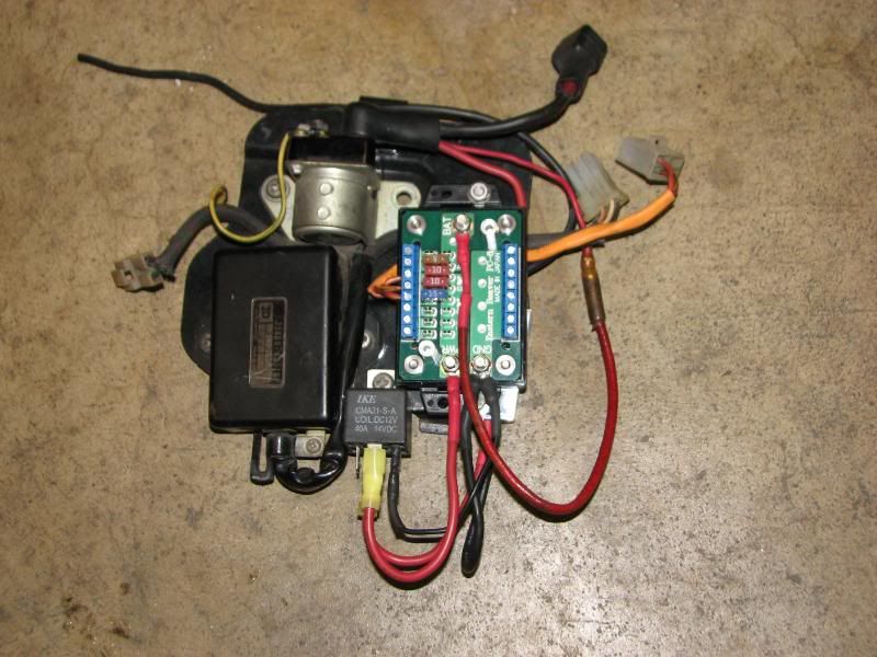
                  here was my suggestion for an interconnect for the PC8; this mirrors the stock GS "T" connection.
                  It includes a SPG. The main difference between the SH-775 and the CF is the finned case/housing of the CF is ground whereas the SH-775 uses a black wire (through the connector) for that ground. You can see two ground wired bolted to the underside of teh case (one on the left and one on the right)


                  Final note, if you look at the schematic above it details out the orientation of the main fuse verses the load fuses. The main fuse is directly connected to the battery (+) so that this fuse is between the R/R(+) and the battery(+). This protects in case the R/R shorts out (which happens with the OEM units and is possible with any unit). The PC8 is constructed so you can orient the right most fuse pair the same way as teh stock GS. I show the "T" connection just above the external relay.

                  As a reminder there is no reason to fuse the output of the R/R. Shorting the R/R has only limited current unlike shorting a battery which creates a welder.

                  Ed's (Nessism) schematic is of course missing much of this detail including a SPG. The SPG is the best configuration to have with degraded (corroded) ground connections. In the case of a Compufire, the SPG is really the case of the R/R.


                  Western_Beaver_Compufire3.jpg
                  Last edited by posplayr; 12-14-2019, 12:43 PM.

                  Comment


                    #10
                    This is a picture of Steve's install of the PC8. The main difference is that he is powering the relay directly from the solenoid post which is the battery (+). This is almost the same thing as my approach, but i woudl prefer to have only one connection to the Batt(+) solenoid post.

                    This does mean that the 30 pin on the relay has to be fed from the small screw terminal (right hand side 15 amp puse) but I presume the PC8 can handle the 15 amp loads through that point.


                    Comment

                    Working...
                    X