Announcement

Collapse
No announcement yet.

Testing rectifier according to factory manual

Collapse
X
 
  • Filter
  • Time
  • Show
Clear All
new posts

    Testing rectifier according to factory manual

    Ok, I've found errors in factory manuals before, but I'm starting to think I'm losing it.

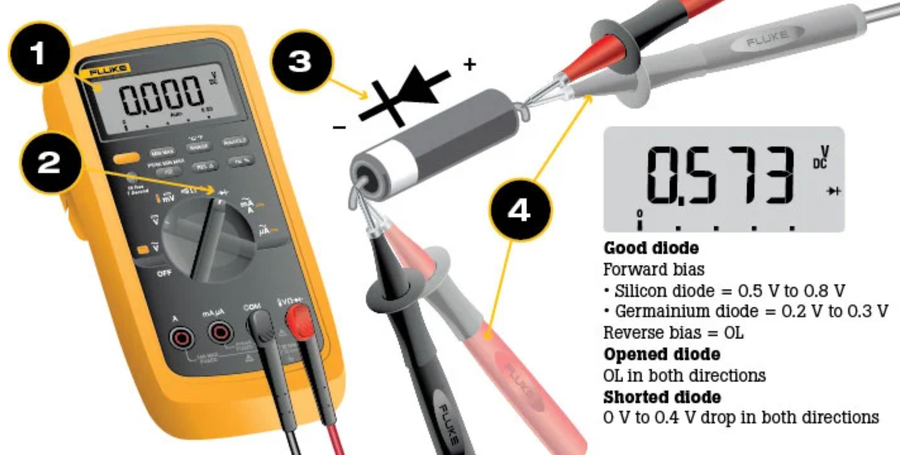
    I was testing the charging system on my old XJ650 Yamaha which is fairly different than the GS but still has a three phase rectifier. I noticed the manual shows the volt meter on resistance and placing the positive probe on the cathode side of diode, the negative probe on the anode and showing there to be continuity. This is opposite for how to forward bias a diode.

    I figure Yamaha just got it backwards by accident. But then I checked my gs250t and gs450 and gs550e manuals and found the same error.

    Were the Japanese meters backwards? Has anyone noticed this? Do I need a nap? I even broke out my old Triplett and Calrad analog VOMs, I still think these manuals are wrong.
    1981 Suzuki GS250T
    1982 Yamaha Seca Turbo
    1985 Suzuki GS550E
    2004 Suzuki GSF1200S

    #2
    Never gave that too much thought. Just figured as long it's effectively open one way and has the required resistance the other way.
    97 R1100R
    Previous
    80 GS850G, 79 Z400B, 85 R100RT, 80 Z650D, 76 CB200

    Comment


      #3
      To check the diodes, you need to check in both directions. One direction will check for opens, the other direction will check for shorts.

      There are six diodes in the rectifier, which means there will be twelve measurements. If any one of them is bad, the entire rectifier is bad.

      .
      sigpic
      mine: 2000 Honda GoldWing GL1500SE and 1980 GS850G'K' "Junior"
      hers: 1982 GS850GL - "Angel" and 1969 Suzuki T250 Scrambler
      #1 son: 1986 Yamaha Venture Royale 1300 and 1982 GS650GL "Rat Bagger"
      #2 son: 1980 GS1000G
      Family Portrait
      Siblings and Spouses
      Mom's first ride
      Want a copy of my valve adjust spreadsheet for your 2-valve per cylinder engine? Send me an e-mail request (not a PM)
      (Click on my username in the upper-left corner for e-mail info.)

      Comment


        #4


        sounds like manuals are wrong for Fluke meters.

        Comment


          #5
          Here: if you want confusion, trust Honda!- note the "note".

          test_hondarectifier.jpg

          Comment


            #6
            Oh, that Honda note makes sense. I will have to keep an eye out for a older Japanese VOM, interesting.
            1981 Suzuki GS250T
            1982 Yamaha Seca Turbo
            1985 Suzuki GS550E
            2004 Suzuki GSF1200S

            Comment


              #7
              well, I just do as Steve said but it doesn't tell you much...and DO see this thread just bbelow,
              Thread: Charging system hasn't failed, should I mess with it?

              page 2 and 3 of this thread https://www.thegsresources.com/_foru...67#post2576867

              where I posted three different R/R diagrams...

              AND in any case, You can't easily bench-test the voltage regulation circuit. SOooo, the best way is to hook the R/R into a bike or just Possibly, comparing diode direction readings with the same model of a "known good" one might tell you if the rectifier is blown but again, tells you nothing about the regulation circuit.

              Comment


                #8
                Never mind the point that most series r/r use dynamic rectification where there is no diode

                Comment


                  #9
                  hmm, Yes, these Series type are using SCRs as rectifiers, aren't they? I haven't aquired a diagram for them yet.

                  I've tried to make setups to test regulation ...cheapo tin aligator clips snaking all over ..it was just an exercise in frustration at my "paygrade" .

                  Comment


                    #10
                    Originally posted by Gorminrider View Post
                    hmm, Yes, these Series type are using SCRs as rectifiers, aren't they? I haven't aquired a diagram for them yet.

                    I've tried to make setups to test regulation ...cheapo tin aligator clips snaking all over ..it was just an exercise in frustration at my "paygrade" .
                    dynamic rectification uses FET with timing to emulate a diode.

                    Comment

                    Working...
                    X