Announcement

Collapse
No announcement yet.

Basic Motogadget M-Unit Wiring Diagram

Collapse
X
 
  • Filter
  • Time
  • Show
Clear All
new posts

    Basic Motogadget M-Unit Wiring Diagram

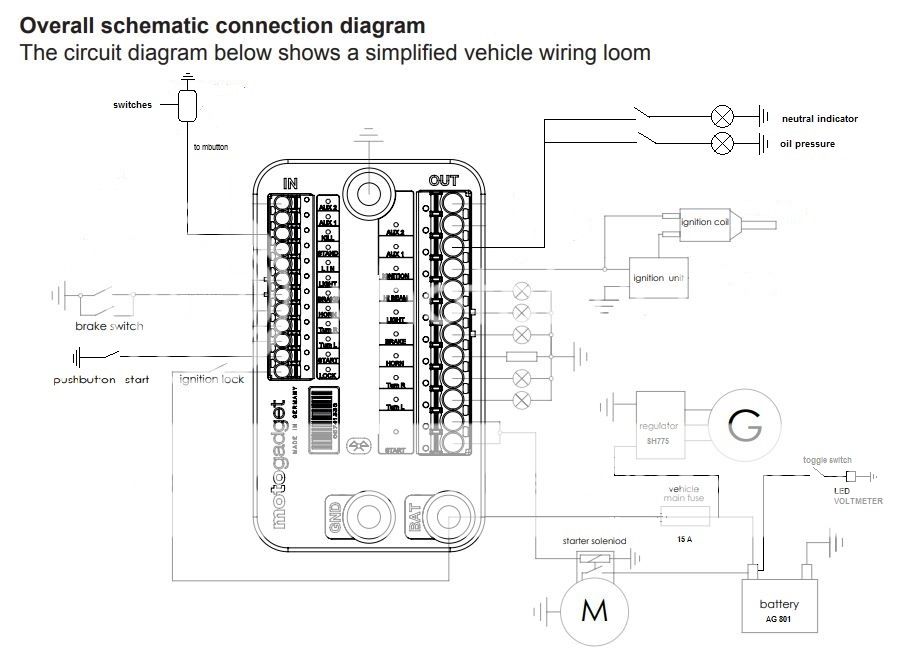
    I am trying to finalize the re-wiring of my 82 GS300 project and I am installing a Motogadget M-unit.

    Does anyone see a problem with this simple diagram? The m-unit related components are according to the m-unit manual.

    Store your photos and videos online with secure storage from Photobucket. Available on iOS, Android and desktop. Securely backup your memories and sign up today!


    The main things I'm concerned about are the wiring for the SH775 R/R and the toggle switch for the LED volt meter.

    Is 30A too large for the battery to handle?

    The goal of the volt meter is to be able to monitor the charging voltage as the bike is running. I have had issues in the past with the R/R going bad and frying other components. I'm also using an Anti-Gravity AG-801 battery which are sensitive to over charging, so I want to protect the battery.

    By monitoring the voltage of the battery itself measure the charging voltage? Or do I need to put the voltmeter between the R/R and the battery?

    Thanks,
    J

    MUnit Diagram_V2.jpg

    #2
    Problem is the picture is too small.

    Comment


      #3
      Originally posted by posplayr View Post
      Problem is the picture is too small.
      Does this link work?

      Store your photos and videos online with secure storage from Photobucket. Available on iOS, Android and desktop. Securely backup your memories and sign up today!

      Comment


        #4
        Originally posted by hjacobmiller13 View Post
        Yes ............ It is bigger

        Comment


          #5
          Two things:
          1.) you have shown liberal use of a groudn symbol without explaining what that is so it is difficult to identify the groudn return path to R/R (-)
          2.) I would recommend the stock GS power distribution strategy of forming a "T" at the input of the R/R (+) and using a single 15 amp fuse. (more the wire from M-Unit -BAT to the "T")

          15 amp fuse is a whole lot better protection than 15 amps, and in this configuration there is typically only 10-11 amps flowing through that fuse.

          Comment


            #6
            I did not open the attachment to see what was there, but a couple other things caught my eye.

            Originally posted by hjacobmiller13 View Post
            Is 30A too large for the battery to handle?
            The fuse does not control the battery. The battery does not control the fuse.
            The fuse is there to protect the bike's wiring, in case a device fails.


            Originally posted by hjacobmiller13 View Post
            The goal of the volt meter is to be able to monitor the charging voltage as the bike is running. I have had issues in the past with the R/R going bad and frying other components. I'm also using an Anti-Gravity AG-801 battery which are sensitive to over charging, so I want to protect the battery.

            By monitoring the voltage of the battery itself measure the charging voltage? Or do I need to put the voltmeter between the R/R and the battery?
            You evidently don't understand the function of a voltmeter.
            If you think of electricity as water, you can think of the voltmeter as a pressure meter. Or you can think of it as a level meter, like a gas gauge. Voltage will remain pretty much the same, wherever you put the meter. If your charging system fails, you will see the voltage ("pressure") drop, but you will not be able to see how quickly it is dropping, which is what an ammeter would do. Taking that analogy a bit further into the fuel gauge scenario, would you rather know that you are using fuel at half a gallon an hour, or would you rather know that you have 1/4 tank left?

            .
            sigpic
            mine: 2000 Honda GoldWing GL1500SE and 1980 GS850G'K' "Junior"
            hers: 1982 GS850GL - "Angel" and 1969 Suzuki T250 Scrambler
            #1 son: 1986 Yamaha Venture Royale 1300 and 1982 GS650GL "Rat Bagger"
            #2 son: 1980 GS1000G
            Family Portrait
            Siblings and Spouses
            Mom's first ride
            Want a copy of my valve adjust spreadsheet for your 2-valve per cylinder engine? Send me an e-mail request (not a PM)
            (Click on my username in the upper-left corner for e-mail info.)

            Comment


              #7
              Thanks for the quick reply!

              I'm not sure I follow your first comment. Everything that shows a ground symbol gets connected back to the negative (-) terminal of the battery, either through a direct connection (engine ground, m-unit GND terminal) or by frame grounding.

              For your second point, is this what you are thinking for the revised diagram?

              Comment


                #8
                I am not expecting the fuse to control the battery or vice versa. I am wondering if a 30A fuse is too high amperage of a fuse in that it will not provide sufficient protection to the battery. I noticed that EasternBeaver uses a 30A fuse between the R/R and battery. I believe the OEM fuse was either a 10A or 15A between the R/R and battery, so an extra 15A fuse will increase the amount of amps that could potentially flow through the circuit before blowing the fuse therefore hurting the battery.

                The purpose of the voltmeter on my diagram is to monitor the voltage of the charging circuit as the bike is running. If my R/R fails and the charging voltage exceeds 14.4v on the voltmeter then I would shut the bike off to protect the other components on the circuit. I'm not sure you understood my question. I am not expecting the voltmeter to provide any protection - just inform me as to the voltage of the charging circuit so I can shut off the bike if the R/R fails. I'm wondering if where I placed the volt meter would only be reading voltage of the battery or just for the charging circuit. I believe that the charging circuit and the battery would have the same voltage but wanted to confirm.
                Last edited by Guest; 06-24-2020, 07:25 PM.

                Comment


                  #9
                  Originally posted by hjacobmiller13 View Post
                  Thanks for the quick reply!

                  I'm not sure I follow your first comment. Everything that shows a ground symbol gets connected back to the negative (-) terminal of the battery, either through a direct connection (engine ground, m-unit GND terminal) or by frame grounding.

                  For your second point, is this what you are thinking for the revised diagram?

                  Yes on teh "T"
                  So your "ground" of battery (-) is the thick starter ground cable?

                  and so where do you run the R/R(-) to the engine or direct to the battery?
                  Your nomenclature is ambiguous a person is left to guess.

                  Comment


                    #10
                    Yes, the engine ground to battery is 6AWG. This is the exact product I used.


                    The R/R would be grounded directly to the battery (-) terminal.

                    Comment


                      #11
                      Originally posted by hjacobmiller13 View Post
                      Yes, the engine ground to battery is 6AWG. This is the exact product I used.


                      The R/R would be grounded directly to the battery (-) terminal.
                      Sorry about the question on the "T". You do not touch anything coming from the BAT + unless it goes through the fuse.

                      The "T" shoudl be on the other side of the fuse.

                      The way you have it, if the R/R shorts you have a fire.

                      You will need to rely on Ed for power and grounding advice.

                      As i said, your schematic is ambiguous as to what you can ground and what connections are to be made.

                      Comment

                      Working...
                      X