Announcement

Collapse
No announcement yet.

Stator phases to chassis resistance?

Collapse
X
 
  • Filter
  • Time
  • Show
Clear All
new posts

    #16
    Oh Boy,
    Broke the magnet,, what a bummer! Well, good luck with the repair. Look on the bright side, at least it CAN be fixed.
    And Duaneage, at first I was shocked (HA) at your post, but then I realized,, your just joking around again! NICE TRY! You almost got me again!

    Comment


      #17
      Originally posted by Keith Winter View Post
      Oh Boy,
      Broke the magnet,, what a bummer! Well, good luck with the repair. Look on the bright side, at least it CAN be fixed.
      And Duaneage, at first I was shocked (HA) at your post, but then I realized,, your just joking around again! NICE TRY! You almost got me again!
      He's not joking. He believes it.

      Comment


        #18
        Originally posted by Boondocks View Post
        He's not joking. He believes it.

        All I can say is hopefully, no one else will. :-)

        E.
        Komorebi-The light filtering through the trees.

        I would rather sit on a pumpkin and have it all to myself than be crowded on a velvet cushion. H.D.T.

        Comment


          #19
          Originally posted by Keith Winter View Post
          Oh Boy,
          Broke the magnet,, what a bummer! Well, good luck with the repair. Look on the bright side, at least it CAN be fixed.
          And Duaneage, at first I was shocked (HA) at your post, but then I realized,, your just joking around again! NICE TRY! You almost got me again!
          Lesson learned: if you think you can finagle the stator cover off without removing your crash bar, think again.

          Comment


            #20
            Ah, yes,
            The dreaded crash bar shortcut rears it's ugly head! Hey, don't feel bad we could have an entire web site devoted to shortcut's gone wrong! I would think almost everyone out there has screwed up at least once in trying a shortcut. I'm guilty of it, and more than one time too! It won't be so bad once it's fixed up and riding down the road, you will all but forget about the mistake. That's why you MUST keep the ruined part's and hang them on the wall next to your bike. By doing this, the next time you are working on the bike and are thinking about a dandy shortcut, you can look at the wrecked parts and re-think the shortcut idea!
            Keith

            Comment


              #21
              Originally posted by Keith Winter View Post
              Ah, yes,
              The dreaded crash bar shortcut rears it's ugly head! Hey, don't feel bad we could have an entire web site devoted to shortcut's gone wrong! I would think almost everyone out there has screwed up at least once in trying a shortcut. I'm guilty of it, and more than one time too! It won't be so bad once it's fixed up and riding down the road, you will all but forget about the mistake. That's why you MUST keep the ruined part's and hang them on the wall next to your bike. By doing this, the next time you are working on the bike and are thinking about a dandy shortcut, you can look at the wrecked parts and re-think the shortcut idea!
              Keith
              It'll probably take more than that the beat the laziness out of me. ;-)

              Comment


                #22
                Originally posted by duaneage View Post
                Considering all the bikes Guy owned I thought he had noticed the screw in the middle of the stator asssembly that provides the circuit ground for the three coils. In order to create voltage you must have flow from ground, through the leg of the stator, and then through the diode. This happens for each leg of the stator. If the screw comes loose in the center that holds it on the bike the stator output goes way down. All current comes from ground, really.

                Now anybody knows the windings and attaching wires don't touch the grounded part of the bike. But when the windings end they must be grounded or it won't work. This has nothing to do with bench testing the part, or even testing the thing with the bike running.

                I suppose I have to dig out my stator mounted to a side cover and snap a few pictures with my ohmmeter connected to settle this. (Sigh)
                Try this, connect your voltmeter black lead to the bike's engine and connect the red lead to ONE of the three yellow stator wires. If you get AC voltage of 30-40 volts then how do you suppose the circuit is being completed?
                Hmmmm.........
                Maybe on duanage's planet they wind their stators in the "star" configuration, but here on Planet Earth it will be found that 3 phase stators are normally wound in "delta" with the three coils wound in series, and always, always isolated from the chassis. If it's wound differently it's an oddity, photo or no photo.

                Comment


                  #23
                  Well,
                  Almost,, but not quite. Our bike's actually use what's called a Wye (Y) and I will quote from the book, Basic Electronics (Grob, fourth edition),
                  Wye, or star, connections. All three coils are joined at one end, with the opposite ends for the output terminals. Any pair of terminals is across two coils in series. The VOLTAGE output of any pair of terminals will be, by trigonometry, the output of one coil, times (X) a factor of 1.73.
                  Delta, or a triangle shape, the three windings are in the form of a triangle. Any pair of terminals is across ONE generator coil. The other coils are in a parallel leg. Therefore, the CURRENT capacity is increased by the factor of, 1.73.
                  None of the coils are DIRECTLY "grounded" in any way. You could get single phase AC out of our three phase stator by hooking one wire up to the common connection, that is where all three coils wires are joined at one end, this would work because at any given time if one set of coils is at positive potential, another set will be at a "negative". We need DC, and that is where the rectifier comes into play. The diodes in the rectifier are a "one way" valve for electrons.
                  When one coil swings positive it "pulls" electrons through it's "positive" diode, through the positive rectifier connection (red wire), through the battery, lights, ignition, ect, through the ground wire or wires and the frame, through the rectifier ground system hooked up to the frame or ground wires and through the "negative" diode in the rectifier that is being supplied by the coil that has swung negative. If we have 3 coils, we need 6 diodes to get all the AC rectified into as much DC as we can.
                  I can't put it any simpler than that, and not be here all night long! I really have to gather up the countless schematics I have, go through all my book's, and synthesize everything into a set of pages, yes WITH PICTURES, and send it in to whoever look's after this stuff for the GSR. After the info is checked to be sure it is CORRECT, it could be posted here, maybe with the stator papers, and that will put an end to all the theories that are floating around out there. I'll make some time, and start this weekend.
                  Keith
                  PS,
                  It should be noted that our stator's have 18 coils, 3 set's of SIX coils. Each set of 6 coils are in series, that is to say, at one end of each set of six there is a yellow (output) and the other end is common, or connected, to the other set's of 6 coils. In my post when I mention, "3 coils" I am refering to 3 set's of 6, or, " when one coil is positive" I of course mean that SET of coils. We have a 3 phase system and each phase is the result of each set of coils. We have 3 phase AC output and 3 set's of coils making it. Sorry if I made it more confusing, it's just that I don't think about how MANY coils there are in there any more!

                  Comment


                    #24
                    Originally posted by Keith Winter View Post
                    After the info is checked to be sure it is CORRECT, it could be posted here, maybe with the stator papers, and that will put an end to all the theories that are floating around out there. I'll make some time, and start this weekend.
                    That would be cool. Perhaps the first myth that could be put down is the notion that it's necessary for the R/R to be grounded (except for heat dissipation). There are only about 400 others ...
                    and God said, "Let there be air compressors!"
                    __________________________________________________ ______________________
                    2009 Suzuki DL650 V-Strom, 2004 HondaPotamus sigpic Git'cha O-ring Kits Here!

                    Comment


                      #25
                      Originally posted by Guy View Post
                      Hmmmm.........
                      Maybe on duanage's planet they wind their stators in the "star" configuration, but here on Planet Earth it will be found that 3 phase stators are normally wound in "delta" with the three coils wound in series, and always, always isolated from the chassis. If it's wound differently it's an oddity, photo or no photo.
                      Stators can be wound in either delta or wye (star) configuration. The instructions in The Stator Papers VI How to rewind your own stator on this site describe a delta configuration. The stator rewound by Nerobro in his excellent writeup Doing the Stator Dance uses the wye (star) configuration.

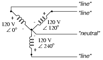
                      The wye configuration is frequently used as a 4-wire three phase setup. At the central point of the wye configuration where the wires are joined together, the voltage is neutral. This point can have a separate fourth neutral wire connnected. This 4-wire system can be used to separate the three phases to three single phase connections by connecting the neutral wire to one of the phases. If it is to be used in full three phase operation, the neutral point can be grounded (or not).


                      At the same rpm, the delta configuration will produce more amperage at lower voltage and the wye will produce more voltage at lower amps. On a wye setup, the voltage between the neutral point and a single phase is the voltage between two legs (phases) divided by 1.732 (the square root of 3). Conversely, if the voltage of a single phase (to neutral) is known, mutiplying that voltage x 1.732 will give the full three phase voltage.


                      There is no "neutral" in delta mode, and voltage between legs is equal.


                      Quote from 3 Phase Basics:

                      There are basically two ways to wire a 3 phase alternator, star ( or Wye) and Delta. With Delta you get lower voltage but more amps. In star you get higher voltage but less amps. You can calculate these by using the square root of 3 ( or 1.732 ). Each coil set is a "phase" of the alternator so when you measure voltage,ohms or current to test one phase of the alternator you would measure the "phase". Once you know what the output will be from one phase you can calculate the "line" output of either delta or star. The line voltage would be measured from any 2 of the 3 outputs. If one phase measured 22 volts in your test and 10 amps then the star configuration would produce 38 volts and 10 amps ( 22 x 1.732 ). The amps remain the same as the phase measurement because the star is basically series'd to another phase. In Delta you would get 22 volts at 17.32 amps (10 amps x 1.73 ). If you calculate this out 22 volts x 17.32 = 381 watts and 38 x 10 = 380 watts... so what is the advantage? Typically the resistance in Delta is 1/3 the resistance of star. If the resistance of star was 1.5 ohms we could calculate the output ( see formula section ). Lets assume the test was at 600 rpm, we achieved 38 volts in star ( about 16 rpm per volt ) so at 1000 rpm we would get 62.5 volts less battery voltage of 12.6 = 49.9 volts / 1.5 ohms = 33.26 amps * 12.6 = 419 watts... not to bad. Now in delta we had 22 volts at the same rpm ( about 27 rpm per volt ). So at the same 1000 rpm we get 37 volts - 12.6 battery = 24.4 volts / .5 ohms = 48.8 amps * 12.6 = 614 watts. Almost a 200 watt gain !!! The advantage of star is the higher voltage at lower rpm which means our unit would have to make 201 rpm to start charging at 12.6V where the Delta would require 340 rpm to start charging.
                      The alternator schematic in the Suzuki factory manual shows the stock alternator wired in wye, presumably for low rpm charging capability. Neverthless, it would appear that the delta configuration might be more useful for a permanent magnet alternator (as used by the Suzuki GS series) at other than very low/idle speeds. In a basic permanent magnet alternator the output voltage rises with rpm and is not internally controlled. Once a charging voltage is gained, extra amps and power capability (watts) would be available with the delta configuration. The R/R dumps current at a cutoff voltage, and the current available below that point would be greater with delta. The downside is that more rpm is necessary to produce a charging voltage. I have read of a more sophisticated hybrid permanent magnet alternator which is wired in the wye mode for low speed charging, and automatically internally switches to a delta configuration at a slightly higher rpm for more charging current. This provides the best features of each configuration.

                      On motorcycles (and all newer cars) with a field coil excited alternator, the wye configuration would allow the charging voltage to rise more quickly at lower rpm while maximum voltage is controlled by feedback to the field coil.
                      Last edited by Guest; 01-05-2007, 06:09 PM. Reason: more information

                      Comment


                        #26
                        Originally posted by robertbarr View Post
                        That would be cool. Perhaps the first myth that could be put down is the notion that it's necessary for the R/R to be grounded (except for heat dissipation). There are only about 400 others ...
                        How did the necessity of grounding the R/R get to be a myth? Did you decide this by yourself? It has been well established empirically that bad grounds are a leading cause of R/R and other charging problems.

                        The factory schematics for the Regulator/Rectifier clearly shows a ground, with current flowing through the ground. When the regulator stops current flow because of voltage limits, the charging current is shunted to ground. Not grounding a R/R is a certain way to cause it to overheat and fail. Shunt-type R/Rs run hot by virtue of their design. Excess R/R heat is removed by cooling fins and not by two bolt holes in a steel frame.

                        Comment


                          #27
                          WELL,
                          First off, Boondocks that is a GREAT post!! I think we had the delta / wye post's going a couple of years ago. I have not been checking this site enough, THAT'S for sure! And I have to admit I have not looked into what's in the "stator papers" here at the GSR. I had rewound my stator, and done everything else to my bike, before I had even heard about this site! I just ASSUMED, based on some of the post's, and alot of the replies, that not enough of the relevent info was in the stator paper's. And now you tell me it's there, well then, I guess I can put all my book's away. And I better go LOOK at what's in the stator papers as well. Also, if it WAS you and I talking about my voltage regulator project, what, 2 years ago now!, it still work's perfect, and the water in the battery is maybe half way down to the "low" line. Not bad for 2 years. Anyway, great post Boondocks, you sure are better at explaining things than I am!
                          Keith

                          Comment


                            #28
                            Originally posted by Boondocks View Post
                            How did the necessity of grounding the R/R get to be a myth? Did you decide this by yourself?
                            I was curious about this, and when the R/R died on my '82 850 I decided to investigate a bit. I bought a new Electrex R/R and explored.

                            First, with a decent digital meter, I tried to find any continuity / path between any of the four wires from the R/R and its case. Every path, in each direction, was infinite. Not exactly a definitive test, and probably it takes a trigger voltage.

                            So I soldered in the original connector to the R/R and attached it to the bike. How to check if it needs a ground, without risking the R/R? I let the R/R dangle without touching the frame and connected an ammeter between the R/R's case and the bike's frame.

                            Started the bike, and no current flow. Tried every combination of electrical loads / engine rpm combos. No current flow. Measured the voltage at the battery, and everything acted about right.

                            I know the ammeter was good because I used it to measure the current delivered by a trickle charger, which is supposed to put out about half an amp. I measured 0.3. Close enough.

                            So, if there's no current flow between the casing and the bike's ground, I concluded that no ground is necessary. With the unit installed, of course, it's bolted to the steel underside of the battery compartment, so it's grounded in operation, but I remain unconvinced that any grounding is needed. Doubting Thomas wants to see the holes.
                            and God said, "Let there be air compressors!"
                            __________________________________________________ ______________________
                            2009 Suzuki DL650 V-Strom, 2004 HondaPotamus sigpic Git'cha O-ring Kits Here!

                            Comment


                              #29
                              Originally posted by Keith Winter View Post
                              WELL,
                              First off, Boondocks that is a GREAT post!! I think we had the delta / wye post's going a couple of years ago. I have not been checking this site enough, THAT'S for sure! And I have to admit I have not looked into what's in the "stator papers" here at the GSR. I had rewound my stator, and done everything else to my bike, before I had even heard about this site! I just ASSUMED, based on some of the post's, and alot of the replies, that not enough of the relevent info was in the stator paper's. And now you tell me it's there, well then, I guess I can put all my book's away. And I better go LOOK at what's in the stator papers as well. Also, if it WAS you and I talking about my voltage regulator project, what, 2 years ago now!, it still work's perfect, and the water in the battery is maybe half way down to the "low" line. Not bad for 2 years. Anyway, great post Boondocks, you sure are better at explaining things than I am!
                              Keith
                              Thanks for the kind words, Keith. I'm glad to hear that your homebuilt R/R is still working so well.

                              While I'm at it, here is a little more delta vs. wye wiring trivia:

                              Delta

                              The internal voltage of a delta wound alternator is higher than a wye winding. This is because each of the three equal single phase voltages is the same as the combined phase line voltage. More insulation on the coil wire for higher voltage protection might add to the weight and size of the stator.

                              A delta winding has a lower internal phase current and less heat loss due to impedance.

                              Total delta line current is 1.732 (square root of 3) X single phase current. A 10 amp single phase current capability is equal to a 17.32 amp line current output.

                              A delta winding is more reliable. If one phase is opened, the line voltage is unaffected. Phase current of the remaining two phases is increased, so the output load should be reduced to 58% of the former maximum to prevent overheating of the remaining two phases.

                              Delta wiring for commercial power generation is not used in Europe.

                              Wye (Star)

                              A wye alternator has greater internal phase current and greater heat losses. Each wye phase carries the full line current.

                              Line voltage of a wye setup is 1.732 X single phase voltage output.

                              The wye configuration and connection is easier to manufacture and rebuild because it is less complex.

                              A wye winding is less reliable. If one phase is opened, two of the phases will have zero volts output.

                              Comment


                                #30
                                Originally posted by robertbarr View Post
                                I was curious about this, and when the R/R died on my '82 850 I decided to investigate a bit. I bought a new Electrex R/R and explored.

                                First, with a decent digital meter, I tried to find any continuity / path between any of the four wires from the R/R and its case. Every path, in each direction, was infinite. Not exactly a definitive test, and probably it takes a trigger voltage.

                                So I soldered in the original connector to the R/R and attached it to the bike. How to check if it needs a ground, without risking the R/R? I let the R/R dangle without touching the frame and connected an ammeter between the R/R's case and the bike's frame.

                                Started the bike, and no current flow. Tried every combination of electrical loads / engine rpm combos. No current flow. Measured the voltage at the battery, and everything acted about right.

                                I know the ammeter was good because I used it to measure the current delivered by a trickle charger, which is supposed to put out about half an amp. I measured 0.3. Close enough.

                                So, if there's no current flow between the casing and the bike's ground, I concluded that no ground is necessary. With the unit installed, of course, it's bolted to the steel underside of the battery compartment, so it's grounded in operation, but I remain unconvinced that any grounding is needed. Doubting Thomas wants to see the holes.
                                The case is just a heat sink. The ground is not the R/R case, it is the ground wire from the R/R. There are not four wires from the R/R for your bike, but five. The black wire with the ring is the ground wire, and should always be connected to the best available grounding point.


                                Wiring Code
                                RED: Positive
                                BLACK: Negative ground ring terminal
                                YELLOW: Phase input from stator

                                Comment

                                Working...
                                X