Announcement

Collapse
No announcement yet.

82' gs1100g gas gauge

Collapse
X
 
  • Filter
  • Time
  • Show
Clear All
new posts

    82' gs1100g gas gauge

    :edit: I decided to edit this first post here so people don't have to slog through to the second page to see the project.
    i appoligize in advance for any spelling and grammar mistakes.
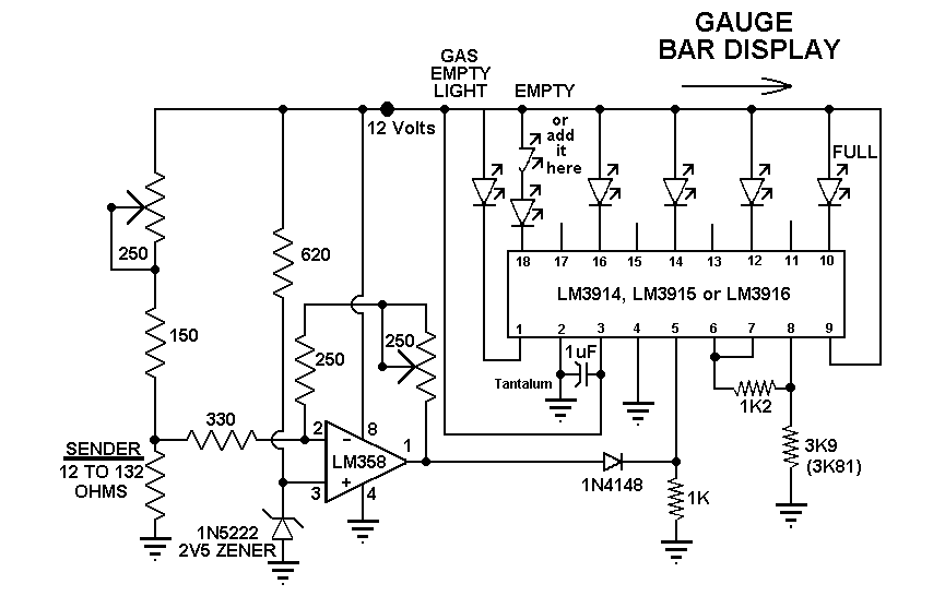
    1982 GS1100G LED Fuel Gauge Project:

    Foreward: the resistances and such represented here are specific to ranges my tank sending unit read out to, however, if you aren't looking for a very accurate fuel gauge, but rather, a tool to decide when to stop for gas, this should work for any sending unit that reads between 1-130ohms. mine read 2 at empty, but i decided to go with 12, as that would give me a little leway.

    plus, there is a spot where something goes, so i figure, put something shiny in there.

    Prep: I searched the internet, and stumbled on a website http://www.electro-tech-online.com .. they have TONS of schematics and people who are knowledgeable about electronics in general. they are like.. the gsresources of bread boards

    having searched their site for a digital fuel gauge schematic, i came across this: http://www.electro-tech-online.com/e...ght=fuel+gauge
    (page 5 has the schematic i am using)


    hmm.. looks like what i need, it has the right resistance ranges.. it's cheap and already laid out. "I'll take it!"
    (note, i am not responsible for designing this, nor am i guarenteeing it's functionality or safety. use at your own risk)

    ok! off to radio shack i go!

    My shopping list, at this point looks like this:

    LM 3914 LED controller
    LM 358 low op amp
    Resistors:
    1/2 watt: 380,330ohms
    1/4 watt: 510,680,1.2,3.9k ohms
    6-10 single bulb LEDs OR 10 LED Bar display
    board to solder to

    a note about resistors:
    you are supposed to read the coloured bands to discern the resistance.

    that link is an excellent resource for that purpose.
    however, I am not very good at it, so i whipped out my volt meter, flipped it to the auto calculating ohms setting, and tested, then marked each set.


    Next, i went looking for the controler chip and low op amp.. radio shack was clueless about them. I looked in the phone book under electronics supply, and found a company http://www.fultonradio.com/. They had what i needed, although the gentleman there ended up cross refrencing with different part number, i looked at the info dump for both chips and am satisfied they preform the exact same function.


    I bought a cheap board from radio shack, they have a large selection to choose from, and as a second thought, 2 small aluminum heatsinks.. since i have no idea how hot these chips will get.

    I don't currently have a soldering iron, but my buddy does, and he's much better at soldering than i am anyhow, so i'm going to have him to that work. I'll get pics of the circuit on the board before and after soldering when i get a little time to get out to his house and slap some hot metal on this thing!
    Last edited by Guest; 03-13-2008, 11:06 AM.

    #2
    Originally posted by seuadr View Post
    this model, from looking at the OEM diagrams had a small gas guage.
    the gauge itself is discontinued according to suzuki, but i had a thought:

    since float guages are pretty much just a measurement of resistance.. what about getting the correct resister range for led bulbs and using those? anyone try this? i know the ready made moduals are pretty expensive, where as buying a control board and the bulbs and resistors myself seems to be pretty damn affordable.

    thoughts?
    Go for it. Post your results. Be the pioneer.
    http://img.photobucket.com/albums/v5...tatesMap-1.jpg

    Life is too short to ride an L.

    Comment


      #3
      I totally want to see this done. I feel a sticky possibility.

      Cory

      Comment


        #4
        Welcome to GSR.

        Yah, you could design something to setup a voltage divider with the differeing resistance of the sensor and then trigger different LEDs at the different voltages levels.

        ... Or you could find a replacement gauge cluster on ebay....

        ... Or you could do like what most other riders do on most other bikes that dont have gas guages and use the trip odometer and the reserve tank of the petcock.
        .
        http://webpages.charter.net/ddvrnr/GS850_1100_Emblems.jpg
        Had 850G for 14 years. Now have GK since 2005.
        GK at IndyMotoGP Suzuki Display... ... GK on GSResources Page ... ... Euro Trash Ego Machine .. ..3 mo'cykls.... update 2 mocykl


        https://imgur.com/YTMtgq4

        Comment


          #5
          ebay

          i had pretty limited luck with ebay, this is an electronic gauge with a bar, rather than a traditional circular gauge. the cluster has a slot for it, and i already have the wiring, so i think i'll give it a go.. worst thing that can happen is simply i spend about 15 dollars on leds and controls

          i'll keep you guys updated on it, assuming i don't catch anything on fire :shock:

          Comment


            #6
            This could be very neat. Looking forward to seeing progress.

            Comment


              #7
              update:

              i did a little searching about the web, and found out alot of information about LED's and how fuel sending units work. I also learned that mechanical fuel gauges are basically relays.. with multiple coils to pull the needle :shock:. never knew that!

              i found a fantastic diagram for exactly what i want to do, with a very, very similar range to the resistance ( my tank was reading between 10 and 120 ohms )


              found a local supply shop here in lansing, the gentleman that helped me was fantastic in finding a similar replacement out of the brands they carry. so far, i've invested a few hours of research, and 14 dollars for parts. i still need to get all the resistors and the zener, as well as whatever system i am going to use for the led bulbs. I've got a few options, i could run a 10 place bar graph, which could be set linear, or as dots to display, or i could make my own mount for individual LED bulbs. haven't decided yet

              Comment


                #8
                Sounds sweet post pics and steps. I may want to do one myself

                Comment


                  #9
                  Originally posted by seuadr View Post
                  I also learned that mechanical fuel gauges are basically relays.. with multiple coils to pull the needle. never knew that!
                  I would like to see your source for the relay information. :shock:

                  The only relay I have ever seen in any system was the relay that switched main power, and precious few vehicles even have that relay.

                  What is 'normal' is more like a regulated 7-volt system that sends current through the meter and the variable resistance of the sending unit in the tank.

                  .
                  sigpic
                  mine: 2000 Honda GoldWing GL1500SE and 1980 GS850G'K' "Junior"
                  hers: 1982 GS850GL - "Angel" and 1969 Suzuki T250 Scrambler
                  #1 son: 1986 Yamaha Venture Royale 1300 and 1982 GS650GL "Rat Bagger"
                  #2 son: 1980 GS1000G
                  Family Portrait
                  Siblings and Spouses
                  Mom's first ride
                  Want a copy of my valve adjust spreadsheet for your 2-valve per cylinder engine? Send me an e-mail request (not a PM)
                  (Click on my username in the upper-left corner for e-mail info.)

                  Comment


                    #10
                    relay

                    i meant the actual gauge on the cluster if it's analog looks very similar to a relay, the coils are charged based on the variable resistance of the sending unit and "attracts" the needle to one side or the other, depending on the fuel level. at least, the one i saw seemed to work that way. it was an analog gauge for a car, though, so motorcycles may be different. rather than calling it a relay, though, i guess i should have called it an electromagnetic coil.. there is no top end to distribute the power, just that, the actual switching mechanism of a relay reminded me of how that analog gauge worked.

                    Comment


                      #11
                      Actually, relays are rather digital in their operation. Yes, you can vary the amount of current through the coil, but nothing happens until it is sufficient to provide enough magnetism to pull the contacts into place, then current flows through the heavy-duty contacts. Essentially, there's enough to activate it or not,

                      You are more correct with the electromagnetic coil idea. Current flows through the coil that is part of the fuel gauge (the needle that you see), which is in a magnetic field. The amount of current is controlled by the resistance of the sending unit. The varying amounts of current cause the needle to deflect more or less, according to the sending unit's position.

                      .
                      sigpic
                      mine: 2000 Honda GoldWing GL1500SE and 1980 GS850G'K' "Junior"
                      hers: 1982 GS850GL - "Angel" and 1969 Suzuki T250 Scrambler
                      #1 son: 1986 Yamaha Venture Royale 1300 and 1982 GS650GL "Rat Bagger"
                      #2 son: 1980 GS1000G
                      Family Portrait
                      Siblings and Spouses
                      Mom's first ride
                      Want a copy of my valve adjust spreadsheet for your 2-valve per cylinder engine? Send me an e-mail request (not a PM)
                      (Click on my username in the upper-left corner for e-mail info.)

                      Comment


                        #12
                        edit

                        i decided simply to edit the first post with an update, so that people don't have to slog back to the 2nd page to get the update.

                        Comment


                          #13
                          haven't given up yet, money is a little tight haven't actually gotten the LED bulbs yet.

                          Comment


                            #14
                            Here is a bar graph array.
                            For such little money I think it's really worth it, especially considering the time saved by not having to mount 10 seperate LED's not to mention the real estate taken up by 10 seperate LED's. I'll see what I can scrounge up at work compnent-wise and put this item on the project list. Gotta get the bike back on the road ASAP tho and I already have a functional gauge.

                            Comment


                              #15
                              aye, i was looking for something like that, but the local shack didn't have any led's at all >< that bar display is actually what the second 20 pin chip was designed to drive.

                              Comment

                              Working...
                              X