Announcement

Collapse
No announcement yet.

How to remove float pins ??

Collapse
X
 
  • Filter
  • Time
  • Show
Clear All
new posts

    #16
    Just to put some closure on this thread...

    I removed all my float pins without incident. I blocked the float post with the pin head through it (taking care not to cover the pin head), wedged a small rectangular piece of aluminum between the two float posts (spaced approx .700" apart), bought a small dia (1/16") flat headed punch and tapped the pins out using a small ball peen hammer - piece of cake!! Absolutely zero stress on the posts!!

    Thanks for all the suggestions guys!!

    Mike
    '85 GS550L - SOLD
    '85 GS550E - SOLD
    '82 GS650GL - SOLD
    '81 GS750L - SOLD
    '82 GS850GL - trusty steed
    '80 GS1100L - son's project bike
    '82 GS1100G - SOLD
    '81 GS1100E - Big Red (daily rider)

    Comment


      #17
      I have used a pair of needle nose pliers in the past with very good results. Just place one side of the pliers to the part of the pin that is sticking out of the post, and the other side of the pliers to the backside of that post. You then can apply quite a bit of pressure to the pin without chancing breaking the post off.

      Comment


        #18
        The poor mans punch - just select a nail or panel pin that is slightly thinner than the float pin. Push the point on the grinder or file it flat, put that on the pin and tap it out gently.

        Comment


          #19
          Originally posted by Doze View Post
          I have used a pair of needle nose pliers in the past with very good results. Just place one side of the pliers to the part of the pin that is sticking out of the post, and the other side of the pliers to the backside of that post. You then can apply quite a bit of pressure to the pin without chancing breaking the post off.
          Yes, I've done that as before - it works when the pin is not that tightly pressed in; mostly likey after someone had taken them out before.

          However, I broke a post that way before - as I learned from this post, the interference fit portion of the pin is the head end. Pushing on the tail end of the pin while securing only the "tail post" (like with the needle nose pliers), leaves the "head post" without any support & susceptible to cracking if the pin is really tightly pushed in.

          I think it's best to always support the "head post" in some fashion to avoid a loud "OH $H1T !!!"

          regards,

          mike
          '85 GS550L - SOLD
          '85 GS550E - SOLD
          '82 GS650GL - SOLD
          '81 GS750L - SOLD
          '82 GS850GL - trusty steed
          '80 GS1100L - son's project bike
          '82 GS1100G - SOLD
          '81 GS1100E - Big Red (daily rider)

          Comment


            #20
            Busted

            Originally posted by Doze View Post
            I have used a pair of needle nose pliers in the past with very good results. Just place one side of the pliers to the part of the pin that is sticking out of the post, and the other side of the pliers to the backside of that post. You then can apply quite a bit of pressure to the pin without chancing breaking the post off.
            I've only broken off one post (one too many). The method you've outlined describes, perfectly, the way I managed to break it.
            1980 GS1100E....Number 15!

            Comment


              #21
              Originally posted by chuckycheese View Post
              I've only broken off one post (one too many). The method you've outlined describes, perfectly, the way I managed to break it.

              So we don't get confused on what needs to be done...

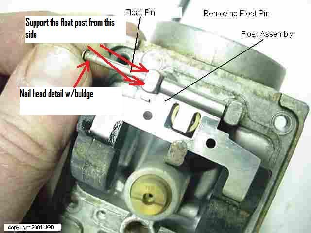
              - The float pin is shaped like a nail, with a bulge under head

              - The bulge under the head of the pin is what creates the interference fit in the float post

              - The float post that is holding the bulged head is the one that breaks off if it's not properly supported during pin removal

              - Float post needs to be supported on the outside edge of the post (the side where the head of the pin abuts)

              - Common methods to support the float post include (based on comments in this post): spread jaws of vice just enough to support the post but allow the pin to move downward, small socket around circumference of the pin head, edge of wooden work bench (or similar piece of soft material or wood).

              - The idea here is to support the post against something solid, while allowing the float pin to be driven downward and out.

              - If you choose to use pliers to remove the pin, you still need to support the float post in some way.

              - Last method that sometimes works is to take a small flat blade screwdriver and lay the blade along side the float post next to the head on the float pin. If you can get the edge of the blade to dig under the head on the float pin, you can pry pin out levering against the post itself. This method works well but most of the time the head of the float pin is abutted against the side of the post so you can't get a blade in there.

              Hope this helps someone.
              Ed

              To measure is to know.

              Mikuni O-ring Kits For Sale...https://www.thegsresources.com/_foru...ts#post1703182

              Top Newbie Mistakes thread...http://www.thegsresources.com/_forum...d.php?t=171846

              Carb rebuild tutorial...https://gsarchive.bwringer.com/mtsac...d_Tutorial.pdf

              KZ750E Rebuild Thread...http://www.thegsresources.com/_forum...0-Resurrection

              Comment


                #22
                My two bits and a picture

                I was totally stuffed as I tried to remove the pin, nothing would shift it (soaking, spraying, hitting it with all type of of pins, screwdrivers)

                I then built a small adaptor which is a modified screw that sits in between the two float towers and hold them firm.

                I then created a small block (black block) that sits under the other carb tower to keep it stable. I also drilled a hole in the block to allow the pin to move out and down.

                I built a small centre punch (not the one shown in the picture) and hit it with a metal hammer.

                Comment


                  #23
                  Originally posted by indyjoel View Post
                  My two bits and a picture

                  I was totally stuffed as I tried to remove the pin, nothing would shift it (soaking, spraying, hitting it with all type of of pins, screwdrivers)

                  I then built a small adaptor which is a modified screw that sits in between the two float towers and hold them firm.

                  I then created a small block (black block) that sits under the other carb tower to keep it stable. I also drilled a hole in the block to allow the pin to move out and down.

                  I built a small centre punch (not the one shown in the picture) and hit it with a metal hammer.

                  .

                  Sorry to sound negative but supporting the float posts like this does nothing. The float post breaks off to the outside, not to the inside. The post that breaks off is the one next to the nail head shape on the pin.


                  .

                  Last edited by Nessism; 01-14-2010, 11:55 PM.
                  Ed

                  To measure is to know.

                  Mikuni O-ring Kits For Sale...https://www.thegsresources.com/_foru...ts#post1703182

                  Top Newbie Mistakes thread...http://www.thegsresources.com/_forum...d.php?t=171846

                  Carb rebuild tutorial...https://gsarchive.bwringer.com/mtsac...d_Tutorial.pdf

                  KZ750E Rebuild Thread...http://www.thegsresources.com/_forum...0-Resurrection

                  Comment


                    #24
                    Originally posted by Nessism View Post
                    Sorry to sound negative but supporting the float posts like this does nothing.
                    That's why he said he had the black block to support the outer edge of the post. He even drilled a hole in the black block so the pin could be driven into it.
                    Originally posted by indyjoel View Post
                    I then created a small block (black block) that sits under the other carb tower to keep it stable. I also drilled a hole in the block to allow the pin to move out and down.

                    .
                    sigpic
                    mine: 2000 Honda GoldWing GL1500SE and 1980 GS850G'K' "Junior"
                    hers: 1982 GS850GL - "Angel" and 1969 Suzuki T250 Scrambler
                    #1 son: 1986 Yamaha Venture Royale 1300 and 1982 GS650GL "Rat Bagger"
                    #2 son: 1980 GS1000G
                    Family Portrait
                    Siblings and Spouses
                    Mom's first ride
                    Want a copy of my valve adjust spreadsheet for your 2-valve per cylinder engine? Send me an e-mail request (not a PM)
                    (Click on my username in the upper-left corner for e-mail info.)

                    Comment


                      #25
                      Originally posted by Steve View Post
                      That's why he said he had the black block to support the outer edge of the post. He even drilled a hole in the black block so the pin could be driven into it.


                      .
                      My comment was in reference to the photo. Supporting the posts on the inside does nothing. Supporting on the outside is good.
                      Ed

                      To measure is to know.

                      Mikuni O-ring Kits For Sale...https://www.thegsresources.com/_foru...ts#post1703182

                      Top Newbie Mistakes thread...http://www.thegsresources.com/_forum...d.php?t=171846

                      Carb rebuild tutorial...https://gsarchive.bwringer.com/mtsac...d_Tutorial.pdf

                      KZ750E Rebuild Thread...http://www.thegsresources.com/_forum...0-Resurrection

                      Comment


                        #26
                        Originally posted by Nessism View Post
                        Supporting the posts on the inside does nothing.
                        Well, it would just be my luck to get a little heavy-handed or have something slip and break the other post, so the little bit of insurance won't hurt.

                        My personal preference is to use some 6" Chanel-loc pliers to span across and press the pin out. Has worked every time, so far.

                        .
                        sigpic
                        mine: 2000 Honda GoldWing GL1500SE and 1980 GS850G'K' "Junior"
                        hers: 1982 GS850GL - "Angel" and 1969 Suzuki T250 Scrambler
                        #1 son: 1986 Yamaha Venture Royale 1300 and 1982 GS650GL "Rat Bagger"
                        #2 son: 1980 GS1000G
                        Family Portrait
                        Siblings and Spouses
                        Mom's first ride
                        Want a copy of my valve adjust spreadsheet for your 2-valve per cylinder engine? Send me an e-mail request (not a PM)
                        (Click on my username in the upper-left corner for e-mail info.)

                        Comment


                          #27
                          I have just removed my float pins on the 650 CVs using a pair of multi grips (I think you guys in the States call them Tongue and Groove Pliers). One jaw on the end of the pin sticking out and the other jaw on the post where the nail head is. And using gentle pressure they came out with a "click" as each one let go.

                          After reading Ed's post I feel I may have been a bit lucky to not have broken the post on one post as it took a lot of pressure to pop it out. Mind you I didn't spray the pin with any lubricant or turn the pin before pressing it out. I will try and do those things next time to be more safe.

                          On a related point what is the best procedure for replacing the pin in the posts. Is it a good idea to run a fine file around the large diameter of the pin so it will be an easier fit. So it will come out easier next time.

                          Just looking at the float bowl, it looks like the shape of the bowl would prevent the pin from coming out under normal riding conditions anyway.

                          Does it need to be the pressure fit that Suzuki used at the factory.

                          Comment


                            #28
                            When the pins are particularly hard to install I don't drive them all the way home. As you noted Don, the float bowl will keep them from falling out so no worry.
                            Ed

                            To measure is to know.

                            Mikuni O-ring Kits For Sale...https://www.thegsresources.com/_foru...ts#post1703182

                            Top Newbie Mistakes thread...http://www.thegsresources.com/_forum...d.php?t=171846

                            Carb rebuild tutorial...https://gsarchive.bwringer.com/mtsac...d_Tutorial.pdf

                            KZ750E Rebuild Thread...http://www.thegsresources.com/_forum...0-Resurrection

                            Comment


                              #29
                              I just slide a razor blade between the post and end with the big head gently slide the blade back and forth till you see a gap between the post and head then take a small screw driver and gently pry the gap larger and the pin will come right out. I have never had a problem or broken a post Good luck

                              Comment

                              Working...
                              X