Announcement

Collapse
No announcement yet.

r/r wiring expert advice, ok?

Collapse
X
 
  • Filter
  • Time
  • Show
Clear All
new posts

    r/r wiring expert advice, ok?

    So I got my new stator today, and installed it it checks out good and puts out 80-82V on all the legs. Hook it to the old r/r 12.9V at 5000rpm, so pull that out and install the new r/r.

    I will tell you how the original wiring diagram shows it wired in.

    2X w/r going to the main power on the fuse box
    2X b going to a ground point
    1X br going to ignition wire(switched)
    3X Y going to the stator


    Here is how I hooked it up

    2X w/r going to the + on battery
    2X b going to the - on battery
    1X br going to the br on the taillight
    3X Y going to the stator

    Start up the bike and it charges 16.5V. Shut off bike.

    Change the wiring

    1X br going to the + o battery

    Start up bike and it charges at 14.55V from 1500rpm up to redline.

    Change wire back to switched wire on bike, now orange on ignition
    Get 16.5V
    Change wire back to battery 14.55V up to 14.6V no higher.


    Wired in a relay that energizes when the key is on to complete the circuit to the + battery post for the brown. Get 14.55V at the battery

    Now what I am thinking is that I am losing too much power in the wiring harnes and the r/r then puts out 16V to get 14V at that point.

    So, by using a relay to energize that brown sensor wire, am I risking setting everything on fire or burning things up. I don't think so, but I want to know what the experts thinks since electrical is my achilles heel.
    Last edited by Guest; 07-14-2008, 09:21 PM. Reason: added bold part

    #2
    That sounds like you have just done exactly what I did to my wife's 850.

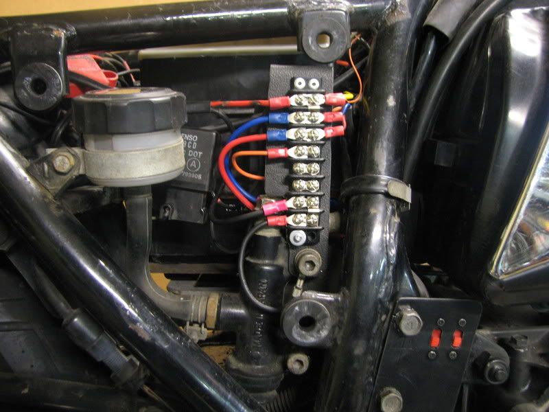
    Since I have added a bunch of electrical accessories, I use that relay to power a terminal strip, then draw power for the accessories from that terminal strip. The top few terminals are switched power, then one row that is constant 12v power, then the LED strip power, a couple of blanks, then a couple of rows dedicated to ground wires for the accessories. This picture was taken about half-way through the install process. It has changed just a bit, but the principle remains the same.
    sigpic
    mine: 2000 Honda GoldWing GL1500SE and 1980 GS850G'K' "Junior"
    hers: 1982 GS850GL - "Angel" and 1969 Suzuki T250 Scrambler
    #1 son: 1986 Yamaha Venture Royale 1300 and 1982 GS650GL "Rat Bagger"
    #2 son: 1980 GS1000G
    Family Portrait
    Siblings and Spouses
    Mom's first ride
    Want a copy of my valve adjust spreadsheet for your 2-valve per cylinder engine? Send me an e-mail request (not a PM)
    (Click on my username in the upper-left corner for e-mail info.)

    Comment


      #3
      Originally posted by Clone View Post
      So I got my new stator today, and installed it it checks out good and puts out 80-82V on all the legs. Hook it to the old r/r 12.9V at 5000rpm, so pull that out and install the new r/r.

      I will tell you how the original wiring diagram shows it wired in.

      2X w/r going to the main power on the fuse box
      2X b going to a ground point
      1X br going to ignition wire(switched)
      3X Y going to the stator


      Here is how I hooked it up

      2X w/r going to the + on battery
      2X b going to the - on battery
      1X br going to the br on the taillight
      3X Y going to the stator

      Start up the bike and it charges 16.5V. Shut off bike.

      Change the wiring

      1X br going to the + o battery

      Start up bike and it charges at 14.55V from 1500rpm up to redline.

      Change wire back to switched wire on bike, now orange on ignition
      Get 16.5V
      Change wire back to battery 14.55V up to 14.6V no higher.


      Wired in a relay that energizes when the key is on to complete the circuit to the + battery post for the brown. Get 14.55V at the battery

      Now what I am thinking is that I am losing too much power in the wiring harnes and the r/r then puts out 16V to get 14V at that point.

      So, by using a relay to energize that brown sensor wire, am I risking setting everything on fire or burning things up. I don't think so, but I want to know what the experts thinks since electrical is my achilles heel.

      Your good as long as BOTH the following are true:

      2X w/r going to the + on battery -- has a fuse in the line on the way to the battery.

      and

      The + wire going to the relay has a fuse in the line going to the battery.

      Comment


        #4
        Um no, no fuse.

        Ok, so on the output, how big a fuse should I use and then on the one from the battery, I figure since it is just a sense wire, 2Amp is ok.

        Just that add a fuse and it is all good?

        Excellent!

        Comment


          #5
          Yeah, I forgot to mention the fuses, too.

          Output on the regulator is probably no more than 20 amps, the original main fuse is 15 amps.
          Considering the size of the wires in the system, I would stick with a 15 amp fuse.

          The sense wire should be small current, I would think something in the 2-5 amp range would be entirely adequate.
          sigpic
          mine: 2000 Honda GoldWing GL1500SE and 1980 GS850G'K' "Junior"
          hers: 1982 GS850GL - "Angel" and 1969 Suzuki T250 Scrambler
          #1 son: 1986 Yamaha Venture Royale 1300 and 1982 GS650GL "Rat Bagger"
          #2 son: 1980 GS1000G
          Family Portrait
          Siblings and Spouses
          Mom's first ride
          Want a copy of my valve adjust spreadsheet for your 2-valve per cylinder engine? Send me an e-mail request (not a PM)
          (Click on my username in the upper-left corner for e-mail info.)

          Comment


            #6
            OK, thanks

            Now have a question, what happens if the fuse on the output blows? Where does all that power that is being generated go?

            If the fuse on the sense wire blows, the voltage will go up to 18V or something like that. I get that.

            I will zip out and get two blade fuse holders to accept a 20 and a 5 and solder them in.

            Comment


              #7
              Originally posted by Clone View Post
              OK, thanks

              Now have a question, what happens if the fuse on the output blows? Where does all that power that is being generated go?

              If the fuse on the sense wire blows, the voltage will go up to 18V or something like that. I get that.

              I will zip out and get two blade fuse holders to accept a 20 and a 5 and solder them in.
              If I remember right, you have your R/R on its own fuse, isolated from everything else ...

              Thats actually very good in the scenario of the main R/R fuse blowing.

              The bike would continue to run, and the battery would run the lights and ignition for a while.

              The voltage on the R/R section would likely go very high, but since pretty much the only thing that could cause the fuse to blow would be a shot R/R, it would be likely to be toasted anyway before the fuse blew.

              And since the high voltage would be isolated from the bike, All your lights and the $$$ ignitor would not be smoked...

              Comment


                #8
                You guys I am sure I am going to ask the last question. The positive from the r/r used to disappear into the wiring harness and it was an 18 guage wire. I assume it goes to the ignition. But there is a lot of voltage lost in the wiring harness. I am going to say 1.5V gets eaten up in the course of running around in there, There is a power point on the fuse panel, should I move the wire from the battery to that point? Since that would be closer to the fuse panel. by running larger wires from the r/r to their termination points I should be reducing the heat load on the r/r, right?
                I am hoping that because this new r/r is just about three times the size of the old r/r (it just fits under the electrical panel) that it can handle a higher load than the 200watts that the stator on these things puts out.

                Comment


                  #9
                  Originally posted by Clone View Post
                  Now what I am thinking is that I am losing too much power in the wiring harnes and the r/r then puts out 16V to get 14V at that point.
                  i'm wondering about the loses on the wiring harness
                  would maybe a thorough cleaning of all the connections result in an acceptable charging voltage at the batery? or you think something else is causing the voltage loss at the sense wire?
                  GS850GT

                  Comment


                    #10
                    I pulled the plugs that were readily accessible, under the tank, by the panel, under the seat, and the big plug under the cluster. Those I blasted with wd40 and squeezed the contacts a bit closer together where they looked spread. The voltage was the same at the brakelight wire. So I can only figure that the harness has built up resistance through the meters of wire in there. All the wire is still supple, the connections don't look heat damaged and the plugs didn't have corrosion in them, just a little dust on the outside of the connectors. So, short of replacing the old harness with a new harness, that is the best I can do there.

                    I figure that some power gets lost in there. After all it all seems to be 20 and 18 guage wires.

                    Comment


                      #11
                      If you follow your wiring diagram (you DO have one, don't you?), you will see that the output from the r/r goes to a point between the fuse panel and the battery. If you are concerned about the size of the wire, just run your 14- or whatever-gauge wire from the r/r straight to the battery or the battery terminal on the starter solenoid (using the fuse, of course). Personally, I prefer to use the starter solenoid and minimize the number of extra wires at the battery terminals. It makes it hard for the isolator caps to cover the terminal if there are extra wires.

                      .
                      sigpic
                      mine: 2000 Honda GoldWing GL1500SE and 1980 GS850G'K' "Junior"
                      hers: 1982 GS850GL - "Angel" and 1969 Suzuki T250 Scrambler
                      #1 son: 1986 Yamaha Venture Royale 1300 and 1982 GS650GL "Rat Bagger"
                      #2 son: 1980 GS1000G
                      Family Portrait
                      Siblings and Spouses
                      Mom's first ride
                      Want a copy of my valve adjust spreadsheet for your 2-valve per cylinder engine? Send me an e-mail request (not a PM)
                      (Click on my username in the upper-left corner for e-mail info.)

                      Comment


                        #12
                        I'm not an expert OK

                        1983 GS 1100E w/ 1230 kit, .340 lift Web Cams, Ape heavy duty valve springs, 83 1100 head with 1.5mm oversized SS intake valves, 1150 crank, Vance and Hines 1150 SuperHub, Star Racing high volume oil pump gears, 36mm carebs Dynojet stage 3 jet kit, Posplayr's SSPB, Progressive rear shocks and fork springs, Dyna 2000, Dynatek green coils and Vance & Hines 4-1 exhaust.
                        1985 GS1150ES stock with 85 Red E bodywork.

                        Comment

                        Working...
                        X