C
Clone
Guest
So I got my new stator today, and installed it it checks out good and puts out 80-82V on all the legs. Hook it to the old r/r 12.9V at 5000rpm, so pull that out and install the new r/r.
I will tell you how the original wiring diagram shows it wired in.
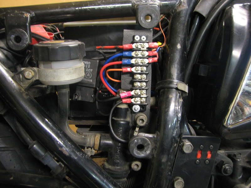
2X w/r going to the main power on the fuse box
2X b going to a ground point
1X br going to ignition wire(switched)
3X Y going to the stator
Here is how I hooked it up
2X w/r going to the + on battery
2X b going to the - on battery
1X br going to the br on the taillight
3X Y going to the stator
Start up the bike and it charges 16.5V. Shut off bike.
:-k
Change the wiring
1X br going to the + o battery
Start up bike and it charges at 14.55V from 1500rpm up to redline.
:-k
Change wire back to switched wire on bike, now orange on ignition
Get 16.5V
Change wire back to battery 14.55V up to 14.6V no higher.
:idea:
Wired in a relay that energizes when the key is on to complete the circuit to the + battery post for the brown. Get 14.55V at the battery
Now what I am thinking is that I am losing too much power in the wiring harnes and the r/r then puts out 16V to get 14V at that point.
So, by using a relay to energize that brown sensor wire, am I risking setting everything on fire or burning things up. I don't think so, but I want to know what the experts thinks since electrical is my achilles heel.
I will tell you how the original wiring diagram shows it wired in.
2X w/r going to the main power on the fuse box
2X b going to a ground point
1X br going to ignition wire(switched)
3X Y going to the stator
Here is how I hooked it up
2X w/r going to the + on battery
2X b going to the - on battery
1X br going to the br on the taillight
3X Y going to the stator
Start up the bike and it charges 16.5V.
Shut off bike.:-k
Change the wiring
1X br going to the + o battery
Start up bike and it charges at 14.55V from 1500rpm up to redline.
:-k
Change wire back to switched wire on bike, now orange on ignition
Get 16.5V
Change wire back to battery 14.55V up to 14.6V no higher.
:idea:
Wired in a relay that energizes when the key is on to complete the circuit to the + battery post for the brown. Get 14.55V at the battery
Now what I am thinking is that I am losing too much power in the wiring harnes and the r/r then puts out 16V to get 14V at that point.
So, by using a relay to energize that brown sensor wire, am I risking setting everything on fire or burning things up. I don't think so, but I want to know what the experts thinks since electrical is my achilles heel.
Last edited: