Announcement

Collapse
No announcement yet.

Electrical question/conundrum

Collapse
X
 
  • Filter
  • Time
  • Show
Clear All
new posts

    Electrical question/conundrum

    Ok, the basics first. 1978 GS1000. My brake lights work, my parking lights work. When I switch the ignition key to "park", the taillights work. When I switch the key to "on", the taillights do not work. My headlight works (High and Low beam).

    Now a few more specifics. My turn signals are not yet attached, Also, my gauge cluster is not attached.

    I bought the bike as a basket case. The wiring was hacked up by the PO. I took the entire loom out of it and went through it wire by wire with the schematic. I tested every connection and repaired anything that was bad. In the process, I also took the self-canceling part of the turn signals out of the circuit and rewired that. I still have not installed the turn signals. I intend to run without the gauge cluster (for now, I may find that I want it).

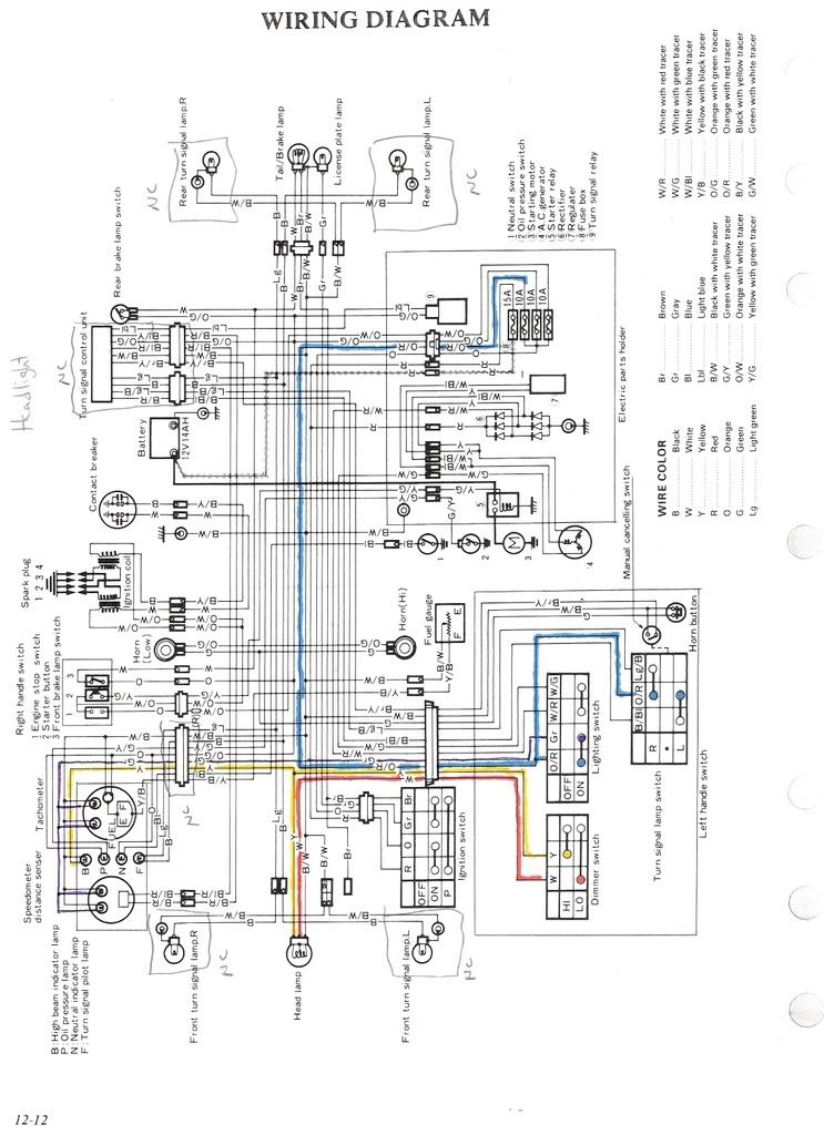
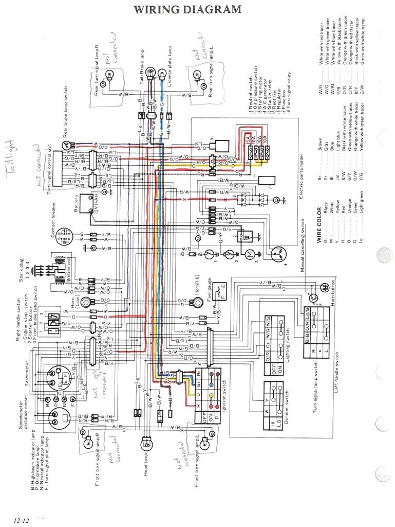
    So, here is where my confusion comes in. I was looking at the schematic for the bike in
    order to trace the fault in the taillight. I used it when I went through loom before, but I did not catch what I am now seeing on the schematic. I don't see from the schematic, how it is even possible to power the rear bulbs other than by the brake switches or by the "Park" setting on the ignition switch. I thought maybe I was just not understanding the schematic (that still may be the case). I took the ignition switch apart to see exactly what combinations it would work under. In the "Park" position it powers the taillight, just like in the schematic. In the "on" position, there is no means for power to go in to either circuit (just like in the schematic). As far as I can tell, everything on the bike is as it should be on the schematic.

    Here is where things get a little weirder for me. As a point of comparison, I thought I'd look at the headlight circuit. It works fine, so I thought therein must lie the answer. Well, according to the schematic, I don't see how it is getting power either. But it works, so it must be getting it from somewhere.

    I have included scans of the schematics with the headlight and taillight circuits highlighted. Can someone please look at this and explain what it is that I am missing? Is this a "ground" thing? Thanks in advance.


    #2
    From what I see the brown wire from the ignition switch powers the rear light. It is a little confusing the way the switch is drawn. Check and see if you get 12+ on the brown wire leaving the ignition switch. Does ur
    rear plate light work ? If no 12+ on the brown wire check the switch. Since
    the head light works the power is getting to the switch. Also check the ground at the bulb socket is it ok ? Hope this helps. You can pm me if you want to follow up.
    Paul

    Comment


      #3
      Looks like your schematics are missing a connection.

      Within the light switch assembly, there is a connection from the gray wire in the lighting switch to those two unconnected terminals in the dimmer switch. That's how the headlight is getting powered. The gray wire is also connected to the brown wire when the ignition is on, powering the taillight.

      There should be a large connector under the front left side of the tank, and you should find that gray wire going into it. Start tracing from there.

      Suspect that gray wire isn't getting back to your ignition switch because you haven't rebuilt that part of the harness yet. Goes through a couple of connectors to get there. Taillight works on park because it is getting powered directly from the red wire.

      Red = 12 V
      Orange = Switched 12 V when ignition is on
      Gray = 12 V to lights when lighting switch is on
      to taillight through ignition switch
      to headlight through dimmer switch
      to other lights directly
      White = Low Beam
      Yellow = High Beam
      Brown = Taillight

      Comment


        #4
        A little more clarification. When the switch is in "Park" it appears that the red wir going in to the switch shorts to the brown wire going out of the switch (the tail light). It checks on an Ohm meter and I have +12 when the switch is in that position. That whole thing makes sense and works as it should. However, when the switch is in the "on" position, that is where it goes wrong. According to the schematic, the ignition switch shorts the Brown wire (Taillight) to the Grey wire (License Light). This kind of makes sense if there is some third source of power to tap in to the two, then they would both light up. But I don't see anything on the schematic that even suggests that there is something. The dimmer switch diagram looks a little funny to me be cause there should be something feeding that too. But the diagram doesn't show it. I did the wiring a couple of years ago and haven't messed with it since. I just put a bulb in this weekend, expecting it to all work (Ha, Ha). So far, I haven't started digging too deep. I always like to get a sense of what things should be before I actually look and see what they really are. If it is incomplete, I'll have to draw it in later. I'll check under the tank and the handlebar switch for the mystery wires that I don't see on the diagram.

        Tomm what part of the harness are you saying that I didn't rebuild? I don't see any way for the gray wire to get to the ignition switch. I bypassed the self canceling signal box and the Instrument cluster is currently not attached, but I don't see that they are related to the taillight (brown wire) and license (grey wire). I must be missing something here.

        Comment


          #5
          When you turn the ignition switch on, the red wire, which is hot from the battery, connects to the orange wire, which feeds the lighting switch.

          When you turn the lighting switch on, the orange wire connects to the gray wire.

          The gray wire connects to the dimmer switch (missing on your schematics) which powers the headlights.

          The gray wire also goes back to the ignition switch. When the ignition switch is on, the gray wire connects to the brown wire, which powers the taillight.

          I suspect your missing the connection from the gray wire coming out of the lighting switch back to the ignition switch.

          Comment


            #6
            BTW - I agree that according to your schematic, neither your taillight nor your headlights will work. But that wiring just appears to be flat out wrong and doesn't agree with typical Suzuki wiring for 1978 GS'es.

            Comment


              #7
              Thanks. I'll check in to it and get back to you. Your diagram looks like what I would expect to see. I was sure I was reading it right, but I've been known to miss things. Like I said, when I went through it, the harness was off of the bike. I checked everything while sitting at my Kitchen table. So, it was really a matter of just finding each wire and verifying continuity and connector condition. I never really questioned the schematic and since putting the loom back on the bike, I've only just this weekend actually put a bulb in the socket and tried to get anything. I'm just now getting to the point where I'm going to plate the bike. It's strange that the diagram is like that, it is supposedly from a factory manual. I'll check some of the other schematics and see if they are the same. Thanks again.

              Comment


                #8
                Hi everyone, I wanted to post an update on this. I dug in to the bike yesterday and I found the issue pretty quickly. The schematic is indeed wrong. Tomm, I tapped in to the gray and the light worked. So, I updated my schematic to reflect the change as well as adding the hot wire that powers the headlight. I never questioned the schematic and just went through the wiring checking everything. When I got the back, the wiring had been a little hacked up. I had to make a few repairs. Yesterday, when I pulled the tank to locate the grey wire, I saw one of my repairs. The PO was an electrical tape junky, He probably lost a connector and electrical taped it. Needless to say, when I came across it, I "fixed" it to reflect the schematic.

                Comment


                  #9
                  I have seen other Clymer schematics with problems, too, so I scrutinized this one and found its problem.

                  Look at the ingnition switch at the bottom of the diagram and the lighting switch in the lower right corner. They both have a gray wire coming out of them. Above the ignition switch (and to the left of the lighting switch) where the two gray wires cross, there should be a dot, showing that there is a connection.

                  Following current from the source:
                  Battery
                  Red wire to ignition switch
                  Orange wire to fuse box
                  Orange/Red wire to lighting switch
                  Gray wire goes to the ignition switch and also feeds all lights except the tail light
                  Brown wire from the ignition switch feeds the tail light.

                  Note that the brown wire is fed by the gray wire when the ignition switch is in the ON position, but by the red wire when the ignition switch is in the PARK position. This is why only the tail light comes on in PARK.

                  .
                  sigpic
                  mine: 2000 Honda GoldWing GL1500SE and 1980 GS850G'K' "Junior"
                  hers: 1982 GS850GL - "Angel" and 1969 Suzuki T250 Scrambler
                  #1 son: 1986 Yamaha Venture Royale 1300 and 1982 GS650GL "Rat Bagger"
                  #2 son: 1980 GS1000G
                  Family Portrait
                  Siblings and Spouses
                  Mom's first ride
                  Want a copy of my valve adjust spreadsheet for your 2-valve per cylinder engine? Send me an e-mail request (not a PM)
                  (Click on my username in the upper-left corner for e-mail info.)

                  Comment


                    #10
                    Originally posted by Steve View Post
                    ... there should be a dot, showing that there is a connection.
                    That's what I determined based on my conversation with Tomm as well. I make a point of updating my schematics as I make changes. So, the schematic has a dot now.

                    Comment

                    Working...
                    X