.png "Powered by vBulletin")
Originally posted by jed.only
View Post
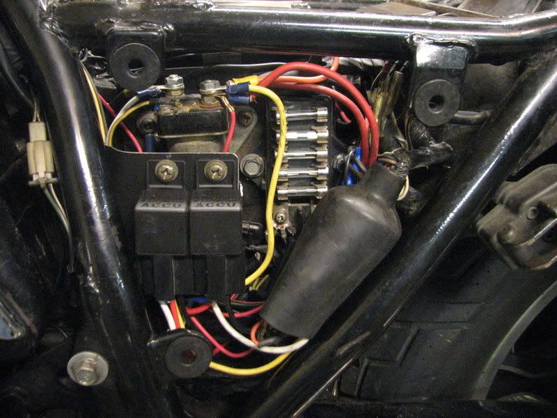
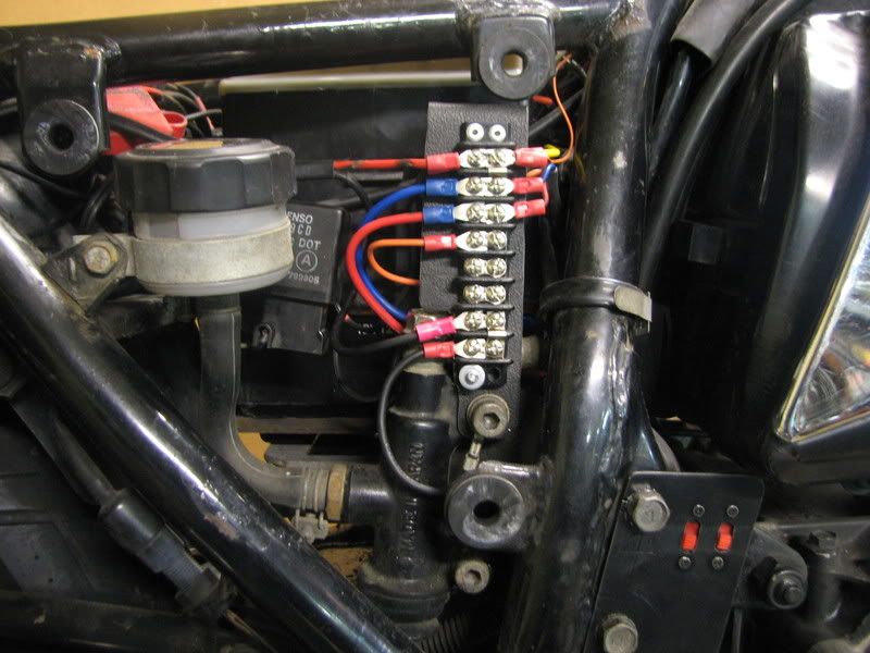
I run one fuse box just for ground.
The second is just for 12 volts Positive.
I could have used a distribution block but separating the grounds and centralizing them gives me an easy way to test each circuit without digging out the harness.
Most of the circuit additions will be low power with the exception of the 139 db horn i just added, so i needed a lot of available fused circuits that were easily accessable,still making the cover for the air horn.
My 12 volt constant is the 4 guage red wire you see going to the fuse box. I still have the original fuse box mounted and i still have a free circuit there to use. I did't want to change things from stock when it came to what was already there, it aint broke why fix it?
The stator output isn't that high to run too many high powered accessories, however i have a distribution block that will provide power from solar panels that will be used to trickle charge main battery when parked in the sun. It will be a 25 watt solar panel which is big so i'll use two smaller ones to provide the needed 1.5 amps
All my upgrades can be seen from the photbucket album linked to my signature as this is an evolving project.


Comment