Announcement

Collapse
No announcement yet.

Coil relay mod with a twist

Collapse
X
 
  • Filter
  • Time
  • Show
Clear All
new posts

    #16
    Originally posted by salty_monk View Post
    As you can see, it really is a true failsafe to carry a jumper cable.
    Agreed.
    I don't think everyone "gets" the fact that you put the relay in a much better location. Under the seat where you can actually get to the relay to troubleshoot, and or bypass it.
    Way better idea IMO.

    Comment


      #17
      At the very least, get a 5-pin relay, with the 5th pin being an 87a.
      That is normally closed when the relay is relaxed, so if the relay fails, simply move your coil wire from 87 to 87a.

      .
      sigpic
      mine: 2000 Honda GoldWing GL1500SE and 1980 GS850G'K' "Junior"
      hers: 1982 GS850GL - "Angel" and 1969 Suzuki T250 Scrambler
      #1 son: 1986 Yamaha Venture Royale 1300 and 1982 GS650GL "Rat Bagger"
      #2 son: 1980 GS1000G
      Family Portrait
      Siblings and Spouses
      Mom's first ride
      Want a copy of my valve adjust spreadsheet for your 2-valve per cylinder engine? Send me an e-mail request (not a PM)
      (Click on my username in the upper-left corner for e-mail info.)

      Comment


        #18
        That would work too with individual wires rather than a relay socket Steve, good idea.

        Jeff - I hadn't thought of that... I forgot a lot of people had these tucked under the tank.

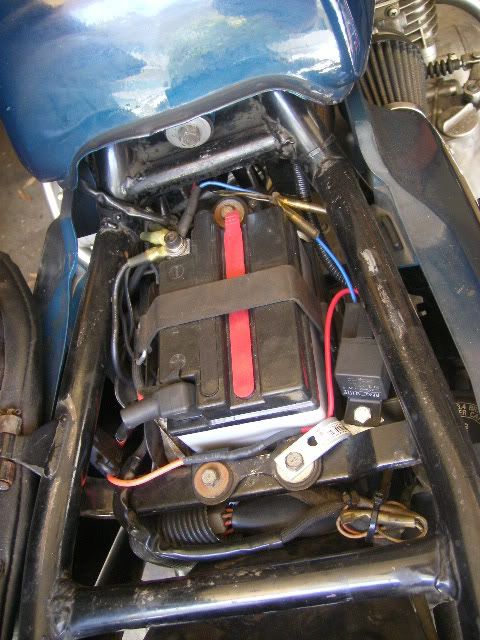
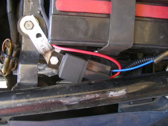
        Some pics of my install:


        Touch wood no probs so far with about 3k miles on it.

        I ran a double wire right up the frame, one goes into the orange white (both of them) where the orange white leaves the main loom (about halfway up the tank) the other one carries on up to the coils. I have a short link between both coils.

        The bracket is only fixed one end to help isolate the relay plus I have it mounted on the rubber battery tray bracket mount which helps too.

        The ground runs direct to battery, the orange wire is a blade fuse holder (you can just see it on the left tucked away) & runs direct to battery.
        1980 GS1000G - Sold
        1978 GS1000E - Finished!
        1980 GS550E - Fixed & given to a friend
        1983 GS750ES Special - Sold
        2009 KLR 650 - Sold - gone to TX!
        1982 GS1100G - Rebuilt and finished. - Sold
        2009 TE610 - Dual Sporting around dreaming of Dakar..... - FOR SALE!

        www.parasiticsanalytics.com

        TWINPOT BRAKE UPGRADE LINKY: http://www.thegsresources.com/_forum...e-on-78-Skunk/

        Comment


          #19
          double redundancy is a ok. electricity finds the least resistance to ground.
          SUZUKI , There is no substitute

          Comment


            #20
            Originally posted by salty_monk View Post
            Jeff - I hadn't thought of that... I forgot a lot of people had these tucked under the tank.
            I did mine pretty much the same way you did on my 1000. I didn't use a relay socket just in case I end up having to use something else while out on the road.
            I made a harness that plugs into the coil/switch circuit, and made a short female to female jumper so I could bypass the relay if it frys in a remote location. That way, other than the extra foot of wire, it's back to stock.

            Also went with the old school glass fuse becuase I already keep spares for the bike.
            ...You won't find many blade fuses at a vintage bike rally.
            Last edited by Guest; 03-13-2009, 04:00 PM.

            Comment


              #21
              Salty

              Originally posted by salty_monk View Post
              If the original problem still exists it's still not an issue.

              As I stated above connect 30 to 87 in the relay socket & you basically hot wire the battery directly to the coils. It will be like having the relay latched permanently.

              That will get you home or to a store for a new relay, just remember to break the connection whenever you stop or you will burn out your coils....

              As you can see, it really is a true failsafe to carry a jumper cable.

              Dan
              I guess I missed the fact you were hot wiring. OK I guess if you need to get home and it is that or nothing. I would still carry the spare relay and resort to the hot wire as a means of last resort. And replace with a relay ASAP. Or remove the jumper if you stop for any amount of time (more that 2-3 minutes).

              My first inclination would have been to jumper the control wire back to the coils and live with the voltage drop. Yes you would suffer the original problem, but you are back to stock function.

              I assume you mounted your relay on the flexible metal extension to reduce shock and vibe to the relay. Wanted to bring that out in case others did not realize that.

              Pos
              Last edited by posplayr; 03-13-2009, 04:21 PM.

              Comment


                #22
                Yes, that & the fact that I needed some kind of bracket to make it fit there whilst still allowing the plastic cover with tool case pocket thing to drop back in
                1980 GS1000G - Sold
                1978 GS1000E - Finished!
                1980 GS550E - Fixed & given to a friend
                1983 GS750ES Special - Sold
                2009 KLR 650 - Sold - gone to TX!
                1982 GS1100G - Rebuilt and finished. - Sold
                2009 TE610 - Dual Sporting around dreaming of Dakar..... - FOR SALE!

                www.parasiticsanalytics.com

                TWINPOT BRAKE UPGRADE LINKY: http://www.thegsresources.com/_forum...e-on-78-Skunk/

                Comment


                  #23
                  I still don't understand why my original question won't work.

                  Posplayr, you said that if I do it my way, the relay won't ever work again? Why?

                  Sure, you'd have 10.5 volts going to 87, but it makes no difference what side the positive is on, whether its 87 or 30. The only thing that controls whether or not the relay will latch is 85 and 86. Neither one of these has any contact with those and shouldn't cause a latching issue.

                  Maybe you could explain it differently?

                  Comment


                    #24
                    MrZig

                    The output is tied to the input and so the input can't drop again.
                    I'm assuming you plan to connect the output of your ignition switch/left hand ON switch (Orange / White) wire to control the relay at say 85 with 86 to GND.

                    You stated you would leave the stock wiring in place (i.e. the Orange / White) connected to the coils +. Since you are also connecting the Normally open 87 to the ignition coils positive , then you have connected indirectly (in the harness) the 85 to 87.

                    When you close the start button, 85 goes to +10.5 energizes the relay coil and pulls 87 to +12V. Since there is nothing to actively pull down 85(+12V stays on 85), when you open the ignition switch , 85 stays high because it is being pulled up by 87 and 87 stays high because 85 high(i.e. latch up at +12V). You have to disconnect the battery to have the relay go back to the open state.


                    The solution to this is to isolate the current flow between 85 and 87 by allowing current to only from from 85 to 87 and not back. The diode performs this function but with a forward drop so now you are at 9.7V instead on 10.5V.

                    Pos
                    Last edited by posplayr; 03-13-2009, 09:56 PM.

                    Comment


                      #25
                      Originally posted by MrZig View Post
                      I still don't understand why my original question won't work.

                      Posplayr, you said that if I do it my way, the relay won't ever work again? Why?

                      Sure, you'd have 10.5 volts going to 87, but it makes no difference what side the positive is on, whether its 87 or 30. The only thing that controls whether or not the relay will latch is 85 and 86. Neither one of these has any contact with those and shouldn't cause a latching issue.

                      Maybe you could explain it differently?
                      Let me give it a shot. I'm not Pos, but I am a practicing EE and understand what he said.

                      Let's start at a point prior to starting your bike. With 86 and 87 shorted together you have power applied to the coils, even with the relay open. Now, you turn on the ignition and the relay closes. At this point you have 2 paths for the current to the coils (the short from 86 to 87 and the closed relay 30 to 87). Still no problem with the bike running.

                      Now it's time to turn off your bike. You remove the normal path for current to 86, but since you have 86 connected to 87 by a short, and the relay is still closed, power is still applied to the 86, through the relay, and it remains closed (until your battery dies).

                      Mock it up and give it a try.

                      Comment


                        #26
                        Originally posted by posplayr View Post
                        I'm assuming you plan to connect the output of your ignition switch/left hand ON switch (Orange / White) wire to control the relay at say 85 with 86 to GND.

                        You stated you would leave the stock wiring in place (i.e. the Orange / White) connected to the coils +. Since you are also connecting the Normally open 87 to the ignition coils positive , then you have connected indirectly (in the harness) the 85 to 87.

                        When you close the start button, 85 goes to +10.5 energizes the relay coil and pulls 87 to +12V. Since there is nothing to actively pull down 85(+12V stays on 85), when you open the ignition switch , 85 stays high because it is being pulled up by 87 and 87 stays high because 85 high(i.e. latch up at +12V). You have to disconnect the battery to have the relay go back to the open state.


                        The solution to this is to isolate the current flow between 85 and 87 by allowing current to only from from 85 to 87 and not back. The diode performs this function but with a forward drop so now you are at 9.7V instead on 10.5V.

                        Pos
                        Yes, a diode would work as you suggested, but let's take this a step further. By adding a diode you only provide a redundant path in case the relay fails. Theoretically, the relay could fail, you wouldn't know it, and you'd run until the diode fails, leaving you in the same position if you didn't carry a spare relay, or a jumper.

                        I guess what I'm trying to say, is that nothing is fool proof. In this case, you're just masking a failed component. Redundant paths are nice in aircraft where circuitry is used to detect failures, so they are addressed before the next flight, but in this case we have none.

                        It would be possible to put something in place, but is it worth it?

                        Comment


                          #27
                          Okay now I understand. The positive from the relay is simply making a long loop back through the relay's trigger keeping it open indefinitely. So there is no way a relay's output can hit a seperate positive source from the same battery or it'll always be a closed circuit. Makes complete sense.

                          Edit: Diagrams help me understand. Durr.
                          Last edited by Guest; 03-13-2009, 10:30 PM.

                          Comment


                            #28
                            Originally posted by reddirtrider View Post
                            I guess what I'm trying to say, is that nothing is fool proof. In this case, you're just masking a failed component. Redundant paths are nice in aircraft where circuitry is used to detect failures, so they are addressed before the next flight, but in this case we have none.

                            It would be possible to put something in place, but is it worth it?
                            They make a click when they work & the 3 that have died on me stopped making a click when they died. On all 3, vibration caused one of the leads on the control side to come off & then short circuited, blowing a fuse. (And then a redundant circuit won't help.)

                            Comment


                              #29
                              Originally posted by p_s View Post
                              They make a click when they work & the 3 that have died on me stopped making a click when they died. On all 3, vibration caused one of the leads on the control side to come off & then short circuited, blowing a fuse. (And then a redundant circuit won't help.)
                              I guess that's my point. Redundant circuits are not worth implimenting unless they are, first, truely redundant, and second, unless you know when the primary has failed and can fix it before the redundant fails.

                              Your leads are falling off due to vibration? No comment.

                              Comment


                                #30
                                Redrider

                                I guess what I'm trying to say, is that nothing is fool proof. In this case, you're just masking a failed component. Redundant paths are nice in aircraft where circuitry is used to detect failures, so they are addressed before the next flight, but in this case we have none.

                                As you say you don't want to mask a failure and that is what you get with redundancy unless you can do Built In Test (BIT) to detect the failures.

                                I think a better solution might be to do a FET relay design and improve the intrinsic reliability. Otherwise just let it fail so you can swap another out.

                                P_S with three failures you should rethink your relay mounting strategy

                                Pos

                                Comment

                                Working...
                                X