Announcement

Collapse
No announcement yet.

GS1000G mods- big bore and fuel injection

Collapse
X
 
  • Filter
  • Time
  • Show
Clear All
new posts

    As an update, I've been working on Microsquirt issues, and hopefully have worked out most of them. The main issue was getting an RPM signal to the unit, which didn't work using the coil. I've since modified the original pickup to operate as two VR sensors and ran a length of shielded cable back to the MS. It seems to be hit or miss on this setup, but at least I was getting an RPM signal. I now need to build a coil driver, since the MS version I have cannot directly control coils.

    There are a lot of variables with this, and there are a lot of different software and firmware versions to make things more interesting.

    The good news for today was I installed fuel pump #2, the first one quit working 4 days after the return period, so I have to send it to Bosch. The better news was it is not leaking. The bad news is the PWM is set too high, as the pump ran up to 50 PSI before I cut it off by hand. I will tweak the settings, but the box I mentioned earlier in this thread has some appeal. The Arudino strikes me as a hobby item, not something for daily use on a bike.

    I have a lot of MS related pics and data, and will post them at some point.
    Last edited by Guest; 04-19-2013, 08:49 PM.

    Comment


      May I make a suggestion to make things easier for you.
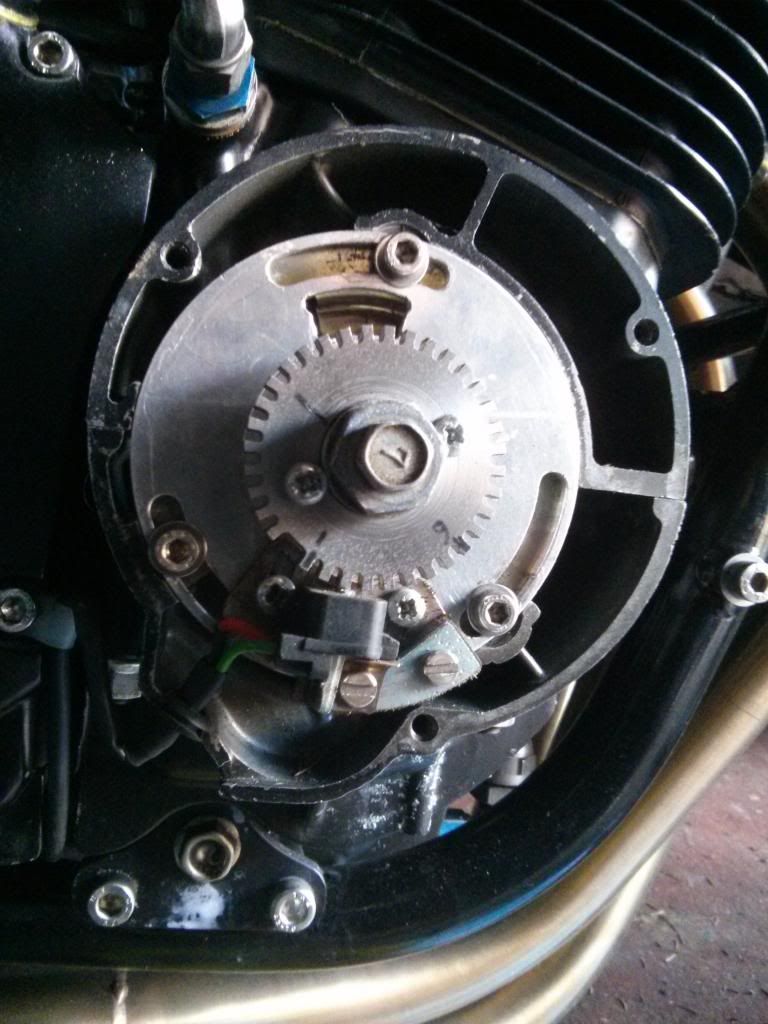
      Get yourself a 36-1 tooth trigger wheel like in the picture below. It works for me & has been used by lots of people doing this conversion.


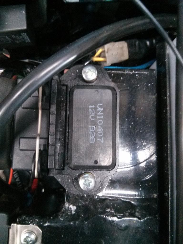
      For the ignition module why not use the Bosch module 0227 100 200 like in the picture below. Again its proven on this type of application so no need to reinvent the wheel. They are fitted to many common cars (VW for example) Wiring instructions are here.


      Another suggestion would be to refit the carbs & get the ignition side of things to work before moving onto the fuel.
      The bonus side of this is now you are using Microsquirt to run the ignition you have the ability to retard the ignition when cranking which will give the starter clutch a much easier time. For me this was an essential part of the whole conversion as I have suffered with exploding starters & clutches for the last 25 years & was why my bike had sat unused since 1998. I just got fed up with it & bought some modern bikes.
      Nick

      Comment


        Great stuff, but looks like $$$. Having to buy two fuel pumps has really hurt the budget. I'll hopefully get some relief if Bosch warranties the first one. I also paid $50 for the aftermarket PWM box when the one I built didn't work properly. A lot of this will be something of a rant, but I think after 21 pages & 200 posts I'm deserving.

        Any idea on the cost of one of those wheels, and related parts or where to find one small enough to fit inside the cover? I searched for a 36-1 motorcycle trigger wheel and eventually found a place called trigger-wheels.com that is overseas. They sell one small enough (2.5" OD) for roughly $30 plus shipping, but then there is mounting it, and relocating one of the pickups (the photo looks like an OEM pickup).

        Looking for that ignition module by part # was likewise frustrating. I eventually found one for $60. The problem with "many common cars" is it returns thousands of parts. If you can specify an application example (i.e. 1985 VW Transporter as I did for the Bosch fuel pump in post #1), this makes it a lot easier to find & find one at a good price. I found one on eBay for $45 shipped, and the application there says 1979-2004 Porsche 911. I had to pull teeth like this for a fuel pump, and really don't want to do it for an ignition module.

        As it stands, I can build a dual circuit coil driver using some perfboard & resistors I had on hand, the old ignitor box (it comes apart easily, also free ), and a couple of $2.60 transistors. I have a spot for it under the seat. I have no room for other boxes at this point, which was a deciding factor for using the ignitor box.

        My point in posting this thread was to make a system that would be repeatable for others that wish to try it using as many common parts as possible.

        I searched here to see if anyone had done this, no sense in re-inventing the wheel. The best thread I found started in May 2009 and 7 pages/ 2 months later in July was more or less abandoned.

        There are no lack of partially completed projects. Here on GSR aside from my thread, there are 22 others with the term "fuel injection" in the title, to include one from April 3 of this year:
        Originally posted by mike10
        I never dreamed it would be that much work!

        Then there are the unanswered questions and ideas floating around. I'm striving to make what I'm doing:
        1. Work,
        2. Be as low-budget as possible, and
        3. Easy to understand for someone reading this 1 week or 1 year later, which is how I approach all projects, be they added gauges or trunk tail lights.

        I'm updating the first post as things change, deleting my posts that are inaccurate or incomplete, and hope to have a clickable table of contents when I'm done. I think I've spent a week or so just bouncing around the various Mega/Micro Squirt versions and pages. I'll see one thing that looks like it may solve a problem, and then when I go to the Tuner Studio software, the setting doesn't exist. I think this is actually worse than learning to speak a foreign language.

        Rant over. I'm feeling better now.

        Comment


          Here is a 0-227-100-200 ignition control module on ebay for $39.95 plus shipping

          http://www.ebay.com/itm/IGNITION-MOD...fabf74&vxp=mtr

          Part looks very similar to the ignition power stage on my 1990 volvo. Its function is to boost the signal from the ignition computer to the coil.

          Comment


            Trigger-wheels.com is where my trigger wheel came from. They are overseas but so am I. The picture I posted is of my set up on what you call a gs1100 katana. Essentially the same bottom end as you. Yes you are correct it uses 1 of the standard Suzuki pickups on a new baseplate & I machined a new carrier for trigger wheel. Its all part of making a nice neat reliable job. None of this stuff has been cheap but the expensive bits are the microsquirt, the wideband controller & the throttle bodies. To do this job properly will cost money but I want everything neat & tidy with no wires & bits sticking out that look wrong (hopefully)
            I saw a similar set up on a forum on a Gsxr which convinced me.
            Regarding the Bosch module the info is out there on the internet.
            I am surprised that you havent found any info on similar projects, granted none on this forum but out in the wide world of the net there are lots of sites that cover fitting Gsxr throttle bodies onto a variety of bikes including a GS & also on bike engined cars. Its all the same thing just a little less room on a bike. Right at the beginning of your post a guy called Arttu offered some help with a pwm controller. He has had a turbo GS running efi on megasquirt since about 2007. He has been a great help to me with info etc. I don't believe that it is really possible to do a step by step conversion guide as most people will have their own ideas on how things should be done. Certainly there are a few things on which you & I would definitely not agree lol.
            I agree with you on the whole megasquirt documentation thing & all the different versions of firmware. I don't expect you to take my word for it but the latest version of ms extra is the way to go & it work well with tuner studio. I couldnt get the ms firmware to work.
            Anyway keep on plugging away & good luck.
            Nick

            Comment


              Converting the GS1000 Ignitor Box

              This post will show how to use the GS1000 ignitor box as a (in this case) coil driver. This came about due to running out of room for extra components. The box could be used for any other purpose so long as the components will fit in. It's about 3" x 2" x 1", so it offers some room for many projects. For the coil driver, most of the stock wiring could have been retained, but it's pointless to be at this stage and not use good quality wire vs 30+ year old wire. This modification will work with the relay mod that is described in another section of the GSR forum. You'll need a pair of Bosch BIP373 coil drivers, and they are only available at one place for about $9. You'll also need perfboard (Radio Shack # 276-1396, about $4) and a pair of 220 ohm resistors (Radio Shack, #271-1313, about $2).

              The box is stamped steel and is basically held together by the 6mm mounting bolts. To take it apart, wedge a small flat tip screw driver between the gold & black parts and the black part will lift off.


              You'll see a circuit board with wires going out. The board is held in place by 4 Phillips screws. Unscrew them and the board can be removed. There is sleeving and a rubber grommet on the wiring harness we can reuse, but you'll have to cut off the connectors to use them.


              Here's the other side of the board once it is removed:


              You can now trace the dimensions onto some nd match/drill the holes so it will mount up in the original location using the original screws. Once installed, it will look like this:


              Here's the wiring diagram:
              Last edited by Guest; 05-04-2013, 09:25 PM.

              Comment


                Sensor data for Tuner Studio software:

                Bias resistor value for temp sensors= 2,490
                Cylinder head temp (temperature in Celsius & ohms) for
                Spectrum Sensors PN GC4914A-3-100:
                0- 162,210
                150- 892.8
                300- 64.87

                Intake air temp (temperature in Celsius & ohms) for
                Vishay PN NTCLE400E3222H:
                0- 7,162
                40- 1,173
                85- 235.5

                MAP (kPa) for
                GM 1 bar sensor:
                0V= 10
                5V= 105

                TPS sensor (count) for
                GSXR600 OEM sensor:
                (The TPS settings will vary by bike)


                O2 wideband sensor (volts & AFR) for
                Bosch LSU 4.2/17014 sensor and Spartan2 controller:
                Set as “Custom linear WB”
                The Spartan 2 controller was designed for a Mega/Microsquirt, and has a process to correct the output. It is located here, but I'll copy & paste the text and hopefully the photos:
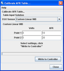
                In Tuner Studio, tools->Calibrate AFR Table->EGO Sensor select "Custom Linear WB", enter the values shown in the picture below (edit: Point 1, 0 volts/AFR 10; Point 2 5 volts/AFR 20) and write changes to MegaSquirt.
                Later on we will change the Custom Linear WB settings to account for offset and linear errors.
                During powerup Spartan 2's Output Sequencer will be triggered, the Output Sequencer will output 2 distinct calibration voltages on the Linear Output, 1.666 volts for the first 5 seconds then 3.333 volts the next 5 seconds, after 10 seconds has passed; the Linear Output will function normally. When a wideband controller is first powered up, it will take about 30 seconds to 1 minute for the Wideband Oxygen Sensor to heat up, while the sensor is heating up the Wideband Sensor is unable to read the AFR of the exhaust gas composition, only when the sensor is heated up will the AFR of the exhaust gas composition be correct. Spartan 2's Output sequencer takes advantage of this heatup time when the AFR data is not correct to output calibration voltages that we will use to generate new Tuner Studio settings to compensate for offset and linear errors.
                While Tuner Studio connected to MS and is actively displaying AFR data, cycle power to Spartan 2 and write down the 2 AFRs shown by tuner studio during the first 5 seconds and then during the next 5-10 seconds. For this example lets use 13 AFR and 17.1 AFR. Now if there were no offset or linear errors present; the first 5 seconds AFR should be 13.328 AFR and the 5-10 seconds AFR should be 16.666 AFR.
                Now download and open this Microsoft excel worksheet here
                Assuming that the first 5 seconds AFR shown by Tuner Studio is 13 AFR and the 5-10 seconds AFR shown by tuner studio is 17.1 AFR, you would enter 13 and 17.1 into the excel worksheet like the above picture, of course instead of 13 AFR and 17.1 AFR you would enter the AFR shown by your Tuner studio. Once those two AFRs are entered, the settings in the green box will be calculated to compensate for offset and linear errors, this calculated setting you will enter into Tuner Studio and your MegaSquirt will be able to read AFRs from Spartan 2 with an accuracy of 1/10th of an AFR.
                In Tuner Studio, tools->Calibrate AFR Table->EGO Sensor select "Custom Linear WB", enter the values shown in green excel worksheet and write changes to MegaSquirt. In my example where the first 5 seconds AFR is 13 AFR and the 5-10 AFR is 17.1 AFR, my calculated new tuner studio settings is 10.89 AFR @ 0 volts and 19.02 AFR @ 5 volts.
                Now if everything was done correctly then now your Megasquirt will be able to read AFR with 1/10th AFR accuracy. Cycle power to Spartan 2 again and now the first 5 seconds AFR should be 13.3 +/- 0.1 AFR and the 5-10 seconds AFR should be 16.7 AFR +/- 0.1 AFR. Because Megasquirt uses only upto the first decimal place to represent AFR, the best you can do is +/- 0.1 AFR accuracy.

                Last edited by Guest; 08-22-2015, 10:35 AM. Reason: Wideband O2 controller setting update

                Comment


                  Originally posted by GS1000G Shopper View Post
                  (Edited for brevity)


                  PVC wire is generally not as high quality, so be sure not to use it where it will see a lot of heat or friction.
                  A side note - PVC wire jacket cold flows, so using any pvc jacketed wire on a weathertite connector system, your wire jacket will deform away from the pressure of the seal, and you will get corrosion at the seal location.

                  Crosslinked polyethylene wire insulation was developed to address this issue (GXL, TXL, etc)

                  -- Mark (sometimes wiring harness engineer, in the olden days)

                  Comment


                    Thanks for the note. Unfortunately I have not found small quantity automotive grade striped wire that is affordable. If you know of a source, I'll be glad to link it.

                    Comment


                      Project is on parts hold again until the PWM controller and parts for the coil drivers get here. Should be by next week.

                      Comment


                        Wiring info due to first post being too long:

                        Wiring
                        Most of my wiring on this project used GM style Weatherpack connectors. I used smaller Mertipack ones on the main connector for the fuel injection harness. The trick setup (discovered after I made my harness) as recommended by another forum member is a place called Corsa Technic. They sell nearly every connector used on Japanese bikes, they are dirt cheap, the connectors include terminals and seals, and they don't charge an arm & a leg to ship. My kind of place. I've bought connectors to make a semi-standalone harness for my GSX-G project.

                        Here's a listing I copied from my GSX-G project document. All part numbers are from either Mouser.com (Microsquirt connector) or Corsa Technic (everything else).
                        A. Microsquirt side (only needed if you want to make a complete standalone harness; this connector will plug into the Microsquirt)

                        Terminals and seals separate
                        1.Microsquirt connector, 35-way: Mouser part #571-776164-1, TE #776164-1. $10.70

                        2. Female terminal (35). Mouser part #571-7708541, TE #770854-1. $.18 each (35)

                        There are 8 wires that go from the Microsquirt to the GSXR600 harness:
                        Injector bank 1
                        Injector Bank 2
                        Sensor ground
                        MAP
                        Cylinder Head Temperature (coolant)
                        Intake Air Temperature
                        Throttle Position Sensor
                        5V reference


                        B. Suzuki side
                        All of these come with terminals and seals
                        1. Main connector, 16-way: Corsa Technic part #HM-16S. $8.16
                        This site has a great selection of oddball connectors at reasonable prices.
                        Mating half of connector: HM-16P
                        From HM Sealed Series
                        Bottom of connector features a bracket mount
                        Typical Application:
                        - Suzuki GSXR injector sub-harness

                        This part will interface with the Suzuki harness. If building a standalone injector harness, also use HM-16P. You can then plug in all 4 injectors and the TPS. You'll need to adapt the MAP and IAT with their own connector. In the alternative, you can test the Suzuki MAP sensor with a vacuum gauge and multimeter and use it as a “custom” MAP in Tuner Studio.

                        Here is the shop manual calibration data for the Suzuki MAP sensor:
                        Altitude: kPa: Volts
                        0-2,000: 100-94: 3.6-3.1
                        2,001-5,000: 94-85: 3.4-2.8
                        5,001-8,000: 85-76: 3.1-2.6
                        8,001-10,000: 76-70: 2.9-2.4

                        In Tuner Studio, the custom MAP needs two values, the kPa at 0.0 volts and the kPa at 5.0 volts. While the manual does not give us this information, it can be obtained as noted above via a vacuum gauge and multimeter or extrapolated using the Suzuki data and a spreadsheet.

                        I'll use an example of a sea-level installation. Since we know 100 kPa= 3.1 volts and 94 kPa=3.6 volts, then the difference of 6 kPa over these 5 points means 6/5 or 1.2 kPa for each .1 volt. A spreadsheet can be used to auto calculate all points from 0.0 to 5.0. In this case, 0.0 volts= 56.8 kPa, and 5.0 volts= 116.8 kPa.

                        Other altitudes can be used by simply switching the data input as above.
                        Here is the shop manual calibration data for the Suzuki IAT sensor:
                        Temp (Celsius): Approximate Ohms (original spec was K Ohms, straight ohms used here)
                        20: 2,450 (range in manual is 2,200 to 2,700)
                        50: 808
                        80: 322
                        110: 148

                        There are 2 empty sockets for the secondary throttle valves, they will not be used. In their place you can use two wires for coolant (head) temperature sensor, and if you want to use the three remaining wires you could use them for a baro sensor.

                        2. a. MAP connector, Suzuki 3 pin. Corsa Technic part #SSC-3S-A $2.41
                        Mating half of connector
                        Tyco/AMP p/n: 184032-1 from Sealed Sensor Connector Series

                        2. b. MAP connector, GM pin. Corsa Technic part #MP150-3S-2 $2.05
                        Delphi p/n: 12129946 from Metri-Pack 150 Sealed series

                        3. TPS connector, 3 pin. Corsa Technic part #MT-3S. $2.03 (not needed if using a factory harness)
                        Mating half of connector: MT-3P
                        Sumitomo p/n: 6180-3241 from MT Sealed Series

                        4. CHT connector, 2 pin. Corsa Technic part #HX090-2S-1. $3.77
                        Mating half not available; OEM Suzuki sensor 13650-10G00, about $58

                        Alternative: MP150.2-2S-2, $2.67
                        Header to mount thermistor:
                        MP150.2-2P-2, $3.38
                        Use thermistor mounted to head, block of aluminum between fins with threaded hole to mount thermistor.

                        5. Injector connector, 2 pin. Corsa Technic part #HX090-2S-2. $3.87 (4)
                        Mating half of connector: HX090-2P-2
                        From HX 090 Sealed Series

                        6. IAT sensor, 2 pin. Uses 2 pin secondary throttle valve connector.
                        Item: MT-2S-1 , $2.36
                        Mating half of connector MT-2P-1

                        Mount IAT Thermistor to:
                        Item: MT2-P-1, $3.16


                        Use quality automotive grade wire. This is called SXL (thick), GXL (regular), or TXL (thin) wire. Here are a couple of inexpensive sources.
                        Motorsports wiring Good prices on SXL/GXL/TXL

                        Performance Connector Systems- Good source for Weatherpack and Mertipack parts

                        British Wiring- PVC wires page, includes striped wire at a good price. Contrary to the name, this is a US company.

                        PVC wire is generally not as high quality, so be sure not to use it where it will see a lot of heat or friction.

                        EDIT
                        I found an informative post on a low-cost method of making your own striped wire using colored Sharpie markers. I tried it on one TXL wire and it seemed to work well enough. First page has been updated with this info.
                        Last edited by Guest; 07-26-2015, 06:51 PM. Reason: Connectors and striped wiring update

                        Comment


                          Just in case anyone wants to use the Bosch ignition module mentioned a few posts back rather than making their own, see the cross ref list below. Please bear in mind the info came from Google so I cannot guarantee it is 100% but I haven't found any errors yet.

                          Beru* 0040401026* 040401026* 40401026* ZM026

                          Bosch 0277 100 200

                          Bosch 0277 100 201

                          Bosch 0277 100 202

                          Bosch 0277 100 204

                          Bosch 0277 100 213

                          Bosch 0277 100 215

                          BMW 12141461441

                          Bremi 14022

                          Alfa 60558153 605581530

                          Citroen 5945.54* 96073612* 9607361280

                          Fiat 605581530* 60809477* 7648798* 76487980

                          Fister* HW670

                          GM 90444650* 90449574

                          Hella 5DA006623601

                          Huco 138401

                          Lucas DAB419 or 21411924

                          Man 51259190017

                          Marelli 940038514* 940038514010

                          Opel 1208074

                          Peugeot 5945.54* 96073612

                          PSA 5945.54* 96073612* 9607361280

                          Valeo 245525

                          Quinton Hazel XEI57

                          Comment


                            Thanks, I'll link that post from the first post.

                            Comment


                              Coil driver box is complete and wired in, the PWM controller is now the holdup. Hoping it will ship soon.

                              I'm thinking there is a better way to DIY this that does not use the Arudino. I see a bunch of PWM controllers on eBay for around $10. They use a potentiometer to control the output. If I were more up to speed on electronics, there must be a way to adapt the 0-5V output of the pressure sensor to replace the potentiometer. Any input from electronics gurus is welcome.

                              EDIT
                              While shopping on eBay, I saw one titled "DC 6V- 90V 15A 12V 24V Max 1000W DC Motor Speed Control PWM Controller". It has a potentiometer that plugs in- most are soldered to the board.

                              I'll attach a photo that shows the potentiometer input. It's labeled ground, 0-5V, and 5V. It seems like this could possibly be wired directly to the pressure sensor, since it uses 0-5V. I need to figure out the corelation between input voltage and PWM output. Does 0V= 0 output or 100% output, and ditto for 5V? As I understand potentiometers, they are variable resistors.

                              If at full resistance the output is 0V, it seems like this would be 0 motor output, which is opposite of what I need it to do. I know I had to invert the input on the Arudino when I wrote the code for it.

                              At < $10 shipped (from China) it would be worthwhile to experiment with it.
                              Last edited by Guest; 04-26-2013, 09:08 AM.

                              Comment


                                The $50 aftermarket fuel pump controller arrived this week, and I'm disappointed. There were NO instructions or a wiring diagram. The online page is ambiguous at best- there are way more wires than needed. The board should have 3x wires from the sensor, this one has 5, apparently 3 are ground, with one data and one 5V power. That's the easy part.

                                The power wiring should consist of 12V & ground in and out to the pump, 4 wires. This one has 8, two pairs of red & black and two pairs of red & green.

                                Additionally, it is just a bare board and unrestrained wires. I'll have to find a small enclosure and rig up a strain relief for the wiring. I have an email in to the supplier to see if he can explain the various wires. I also sent a wiring diagram based on my best guess and his online instructions. I'll post it here once I sort it out.

                                He has the market cornered on this for now, the least expensive alternative is a lot more expensive. Some are over $300.

                                Here's a pic of the unit as received:


                                UPDATE
                                Here is the correct wiring diagram, with my notes at the bottom.


                                Here is the small Radio Shack enclosure #270-1801, it's the smallest one they sell, 3" x 2" x 1", about $3.50. I used a couple of 3/8 x 1/4 rubber grommets to run the wires through. I had to smooth the inside of the enclosure since it has ribs for board mounting. The board press-fits in the standoffs, and I used a small amount of adhesive to hold it in place. I used two small zip ties for strain relief. I topped it off with a label for future reference. Upon use, my pressure gauge showed it was set to about 48 PSI, so I bumped it down a little via the "down" button.


                                Last edited by Guest; 05-04-2013, 03:44 PM.

                                Comment

                                Working...
                                X