Announcement

Collapse
No announcement yet.

More coil relay mod help....

Collapse
X
 
  • Filter
  • Time
  • Show
Clear All
new posts

    More coil relay mod help....

    Well I got all the stuff for the mod and already hit a snag.

    I opened up my wiring harness and instead of having all 4 orange/white wires coming together into one like the tutorial says, I have 3 that all join to one above the carbs and the 4th just runs past that junction further into the wiring harness. Do I need to keep cutting further back in the harness and will find a spot where the 4th joins the wire feeding the other 3? Wiring is not my thing and any help would be appreciated.

    Bike: 1982 GS550L


    One other question when testing the front primary (i think) side both coils show about 4 ohm but when I test the other side (via plug boot and one wire from coil) I get 0 ohms. Is this right?

    #2
    Originally posted by xxBenJamminxx View Post
    Well I got all the stuff for the mod and already hit a snag.

    I opened up my wiring harness and instead of having all 4 orange/white wires coming together into one like the tutorial says, I have 3 that all join to one above the carbs and the 4th just runs past that junction further into the wiring harness. Do I need to keep cutting further back in the harness and will find a spot where the 4th joins the wire feeding the other 3? Wiring is not my thing and any help would be appreciated.

    Bike: 1982 GS550L


    One other question when testing the front primary (i think) side both coils show about 4 ohm but when I test the other side (via plug boot and one wire from coil) I get 0 ohms. Is this right?
    If you look at your schematic, the O/W is the ignition circuit which powers both coils and the ignitor. You should power all three. You only need to separate the O/W circuit from the power coming from the Kill switch. Replace that with power coming from your new relay.

    So more than likely the wire continues into the harness to get to the ignitor. You can confirm by using an ohm meter on the ignitor plug to the 3 wire joint.

    Actually you don't need to open up the harness, you can usually cut the Kill switch power at the (right hand switch)connector.

    This includes the Dyna S control, but if you ignitor that part the rest still applies. Get rid of your Stator Loop from the R/R to left hand switch and you will free up a wire inside of the harness to route the kill switch signal to a relay mounted in back.

    Technical Info posts that are deemed to be important or popular will be placed here for easier access. If you feel a post should be moved from the Technical Info forum to here then PM the Administrator with your request.
    Last edited by posplayr; 06-14-2013, 03:34 PM.

    Comment


      #3
      Sorry I am not sure I follow.


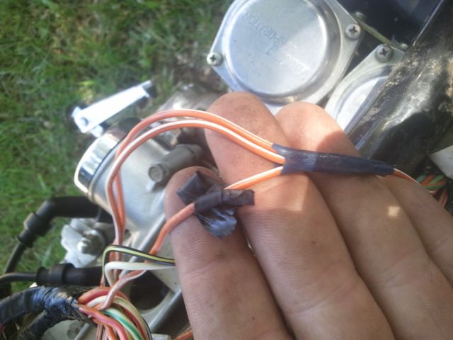
      Here are the 3 wires that go into one. The one with black tape on it shows power with the kill switch in the run position and no power in the off position. Other 2 go to the coils.


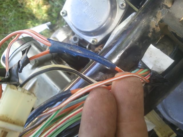
      Here is the 4th wire that runs into the harness further. Are you saying I cut the wire that only has power on run and run that into the number 86 on the relay, 85 would be a new ground I make, 87 would be BOTH the wires that go to the coil, and 30 comes from the battery with a fuse on it?

      Comment


        #4
        Originally posted by xxBenJamminxx View Post
        Sorry I am not sure I follow.


        Here are the 3 wires that go into one. The one with black tape on it shows power with the kill switch in the run position and no power in the off position. Other 2 go to the coils.


        Here is the 4th wire that runs into the harness further. Are you saying I cut the wire that only has power on run and run that into the number 86 on the relay, 85 would be a new ground I make, 87 would be BOTH the wires that go to the coil, and 30 comes from the battery with a fuse on it?
        When I put in the coil relay mod, I abandoned ALL those wires. Ran all new ones in a heavier gauge.

        Comment


          #5
          So do i hook up the wire from kill switch that only has power to 86, power to 30, ground to 85 and then just hook new wires from 87 to the O/W leads going into the coils?

          Waiting before I start cutting anything....

          Comment


            #6
            Alright so I have power to the relay and up to the coils if ground it out on the battery but if test from power wire to coil to the ground (black or white) wire I get no power. Therefor obviously I have no spark right now after hooking it up.

            Should I have to take the ground wires from the coils and ground them as well since I cut the O/W wires going to the coils and am powering them via a new wire off the relay (terminal 87)

            Comment


              #7
              Now for the heck of it I tried cutting the grounds and running them directly to the neg terminal on the battery and still no spark.

              What did I do wrong now... so much for it takes as much time to remove the seat and tank as it does the mod. hahaha

              Comment


                #8
                Originally posted by xxBenJamminxx View Post
                Now for the heck of it I tried cutting the grounds and running them directly to the neg terminal on the battery and still no spark.

                What did I do wrong now... so much for it takes as much time to remove the seat and tank as it does the mod. hahaha
                The coil grounds are left alone. Your post (#5) looked right on to me.

                Comment


                  #9
                  Originally posted by xxBenJamminxx View Post
                  Sorry I am not sure I follow.


                  Here are the 3 wires that go into one. The one with black tape on it shows power with the kill switch in the run position and no power in the off position. Other 2 go to the coils.


                  Here is the 4th wire that runs into the harness further. Are you saying I cut the wire that only has power on run and run that into the number 86 on the relay, 85 would be a new ground I make, 87 would be BOTH the wires that go to the coil, and 30 comes from the battery with a fuse on it?
                  First off if all 4 wires are connected then you can't really tell which one is powering the set unless you disconnect the one that is powering the set.

                  So if you did not cut any wires then you don't have a valid test to find out which wire is coming from the kill switch. I know you have torn your harness apart according to the directions (you found) but there was really no need.

                  Putting that aside, if you want to work from the splayed out harness then work your way with the O/W toward the front of the bike that is where the Kill switch is located. You should be able to identify the O/W that goes to each coil. You need to cut before the kill switch signal gets to the coils so move in front of the coils to do your cut.The other end that goes toward the back of the bike is for the ignitior.

                  Once you decide which is the front of the bike and what O/W goes with that, but the wire. Then the Front part of the O/W cut should follow the power from the kill switch. The back side of the O/W cut should stay open.Then make the following connections

                  Pin 30 - Fused Battery (+)
                  Pin 87 - Back O/W cut**
                  Pin 86 - Front O/W cut**
                  Pin 85 - Ground

                  **Cut is to separate the ignition circuit(from coils to the back of the bike) from the kill switch toward the front of the bike (on handlebars).

                  This is really quite easy and you don't have to change any wires. As i said I don't even open up my harness just cut the kill switch line that is powering the ignition circuit.

                  While you have the harness open you should find the crimp where the wires connect and flow some solder into the crimp. If it is oxidized you may have to clean it with some naval jelly or other contact cleaner.
                  Last edited by posplayr; 06-14-2013, 08:57 PM.

                  Comment


                    #10
                    Originally posted by 850GT_Rider View Post
                    When I put in the coil relay mod, I abandoned ALL those wires. Ran all new ones in a heavier gauge.
                    Generally it dirty or corroded contacts and connections that cause problems not the actual wire size.

                    Comment


                      #11
                      Originally posted by xxBenJamminxx View Post
                      Now for the heck of it I tried cutting the grounds and running them directly to the neg terminal on the battery and still no spark.

                      What did I do wrong now... so much for it takes as much time to remove the seat and tank as it does the mod. hahaha
                      The coils spark when the ignitor opens a coil leg one at a time. If you grounded both directly to the battery, it ain't gonna work. Please don't get any more urges to experiment like that lest you do some actual damage.

                      Comment


                        #12
                        Originally posted by posplayr View Post
                        Generally it dirty or corroded contacts and connections that cause problems not the actual wire size.
                        oh yeah - understood. But when I cut off the cruddy connectors to replace them, didn't like the corrosion and discoloration I saw wicking it's way up the conductors. Decided just to abandon them in place. Went up on size wire gauge, just because....that's the wire I had.

                        Comment


                          #13
                          Ok thanks for the help guys. I must be making this harder then it has too. Let me recap what I think I know and see if you guys think Im on the right track here.


                          In this picture the O/W wire with the piece of tape I believe is the one coming back from the kill switch since it only shows 12.6v with the kill switch in the run postion. When on kill it shows 0.0v. The other 2 O/W wires next to that one go directly to the coils.


                          In this picture is the other O/W wire runs along along the other 3 and runs past where those 3 come together and are spliced into one. Is this the igniter wire?

                          So here is what I did so far.....

                          I made a new power wire with a 20 amp fuse inline to the relay terminal #30. I made a new ground to the frame and goes to the relay terminal #85. I cut the 2 O/W wires right in front of the coil wire plugs and spliced them together and then they go the relay terminal #87. Then I took the wire with the tape on it (which I thought was from the kill switch) and cut that and attached it to the relay terminal #86.

                          With that setup I was getting 12.5v to each coil right where the wire goes into the coil itself IF I grounded my volt meter to the neg side of the battery, but didnt get any spark from either coil. If I probed the other wire coming from the coil (again thinking it was a ground for the coil) I got nothing. So thinking that was a ground wire for the coils I cut them and put them directly to the neg terminal on the battery to see if that gave me spark, which it did not.

                          So was I wrong in thinking that the other wire (not the O/W) from the coil is not a ground but rather the wire coming from the igniter? If this is from the igniter should I reconnect those to 2 to the original wires instead of to the batteries neg side? Also if that is from the igniter do the coils just get their ground from where they bolt to the frame?

                          I guess I need the idiots guide here as I am not sure whats up here. Thought I had it figured out but after reading a few different tutorials I may have been thinking of this all wrong.

                          Thanks in advance, and am hopign to get back into the garage tonight and get this straightened out yet tonight.

                          Comment


                            #14
                            Originally posted by xxBenJamminxx View Post
                            Ok thanks for the help guys. I must be making this harder then it has too. Let me recap what I think I know and see if you guys think Im on the right track here.


                            In this picture the O/W wire with the piece of tape I believe is the one coming back from the kill switch since it only shows 12.6v with the kill switch in the run postion. When on kill it shows 0.0v. The other 2 O/W wires next to that one go directly to the coils.


                            In this picture is the other O/W wire runs along along the other 3 and runs past where those 3 come together and are spliced into one. Is this the igniter wire?

                            So here is what I did so far.....

                            I made a new power wire with a 20 amp fuse inline to the relay terminal #30. I made a new ground to the frame and goes to the relay terminal #85. I cut the 2 O/W wires right in front of the coil wire plugs and spliced them together and then they go the relay terminal #87. Then I took the wire with the tape on it (which I thought was from the kill switch) and cut that and attached it to the relay terminal #86.

                            With that setup I was getting 12.5v to each coil right where the wire goes into the coil itself IF I grounded my volt meter to the neg side of the battery, but didnt get any spark from either coil. If I probed the other wire coming from the coil (again thinking it was a ground for the coil) I got nothing. So thinking that was a ground wire for the coils I cut them and put them directly to the neg terminal on the battery to see if that gave me spark, which it did not.

                            So was I wrong in thinking that the other wire (not the O/W) from the coil is not a ground but rather the wire coming from the igniter? If this is from the igniter should I reconnect those to 2 to the original wires instead of to the batteries neg side? Also if that is from the igniter do the coils just get their ground from where they bolt to the frame?

                            I guess I need the idiots guide here as I am not sure whats up here. Thought I had it figured out but after reading a few different tutorials I may have been thinking of this all wrong.

                            Thanks in advance, and am hopign to get back into the garage tonight and get this straightened out yet tonight.
                            You are close, but unfortunately no cigar; you apparently cut in the wrong place and thereby isolated the ignitor which I'm guessing is not powered.

                            If you look at the attached drawing you should be able to realize why it is not necessary to open the harness. You have to cut separate the whole ignition circuit from the kill switch. (to the left of the connector). I drew in the relay also.

                            Comment


                              #15
                              Ok so from the diagram I think I have the wrong wire that comes from the kill switch since the one I used was bundled up with the other 2 that came from the coils. Which I think is the o/w wire that is between the coils and the igniter. I just figured since the other o/w wire had power whether the kill switch was on or off that was the power feeding to the kill switch and the other one which I cut was coming back from it. I am gonna go out and double check my stuff, but dont know if I should reconnect it back up as it was stock and then start over or what.... Wishing I never started this project now. Something so simple has me so stumped. Did i mention I hate wiring.

                              Comment

                              Working...
                              X