Announcement

Collapse
No announcement yet.

oversize valve install 4valve gs

Collapse
X
 
  • Filter
  • Time
  • Show
Clear All
new posts

    oversize valve install 4valve gs

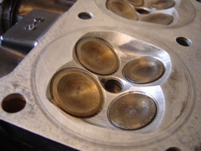
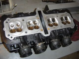
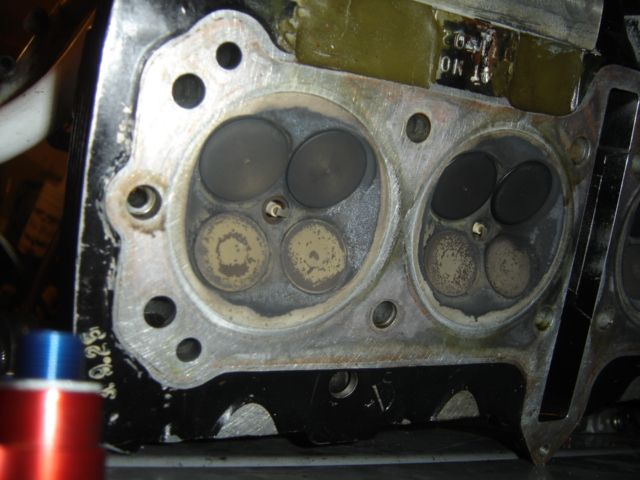
    just a note to begin i understand this is hard earned and valuable info and if anyone chooses not to share i understand that being said im asking for help and right or wrong im giving it my best shot im installing oversized 28.5 valves in a gs 1100 head and im wondering on the combustion chamber side of valve what is needed to unshroud the valve head seems like not just an area on the chamber wall is pretty close but also all the way around the valve the aluminum pocket around the valve is close
    Now -to those considering weather or not to do this on a performance build i assure you you should
    from the original seating and throat size on the valve from the factory to a performance job seating on the outer edge of a 1.5 mil larger valve there is a big increase in area
    Thanks in advance for any help you can be and of course pice would be awsome

    #2
    Merry Christmas
    Technical Info posts that are deemed to be important or popular will be placed here for easier access. If you feel a post should be moved from the Technical Info forum to here then PM the Administrator with your request.


    You can flow just as much with a 28mm or even 27mm depending upon the porting

    Comment


      #3
      Originally posted by posplayr View Post
      Merry Christmas
      Technical Info posts that are deemed to be important or popular will be placed here for easier access. If you feel a post should be moved from the Technical Info forum to here then PM the Administrator with your request.


      You can flow just as much with a 28mm or even 27mm depending upon the porting
      thank u much a good helping start anybody else have pics of there chambers where a pro has installed oversized valves

      Comment


        #4
        29 intake on a 28 seat

        http://,

        http://

        I use Neway cutters to do the seats and a high speed rotary tool to do the aluminum. - don't go crazy - just a little eyebrow work - this head intake flow is a tad over 100 CFM@.400 and I use drop in .348" cams -not decked - nothing too fancy just built to last for decades and run a #730 vehicle package to the 9.3s' range and 9.4 in the summer heat with a set of RS 36 feeding 1428 pistons - might be 10.0 to 1 ,, I have a very thick base gasket . clearance is .052" under - and then the .046" head gskt. - safe enough.
        SUZUKI , There is no substitute

        Comment


          #5
          Originally posted by trippivot View Post
          http://,

          http://

          I use Neway cutters to do the seats and a high speed rotary tool to do the aluminum. - don't go crazy - just a little eyebrow work - this head intake flow is a tad over 100 CFM@.400 and I use drop in .348" cams -not decked - nothing too fancy just built to last for decades and run a #730 vehicle package to the 9.3s' range and 9.4 in the summer heat with a set of RS 36 feeding 1428 pistons - might be 10.0 to 1 ,, I have a very thick base gasket . clearance is .052" under - and then the .046" head gskt. - safe enough.
          thanks this really helps looks like you left the area-ring around the valve completley alone this is the very area im wondering about wondering how this ring aroud the valve effects low flow just seems like at say .040 or so lift it would be restrictive

          Comment


            #6
            If you looks at this post, the other Terry got 100 CFM on the intake with 27mm valves on an 83 head.
            Technical Info posts that are deemed to be important or popular will be placed here for easier access. If you feel a post should be moved from the Technical Info forum to here then PM the Administrator with your request.


            My sheet (I just found) shown 96.4 CFM (@ 0.400") with 28mm 1150 intakes on 82/83 head. I told him to be less aggressive with my head

            Comment


              #7
              Originally posted by posplayr View Post
              If you looks at this post, the other Terry got 100 CFM on the intake with 27mm valves on an 83 head.
              Technical Info posts that are deemed to be important or popular will be placed here for easier access. If you feel a post should be moved from the Technical Info forum to here then PM the Administrator with your request.


              My sheet (I just found) shown 96.4 CFM (@ 0.400") with 28mm 1150 intakes on 82/83 head. I told him to be less aggressive with my head
              did he explain how the small ex valve so dramatically outflows the intake at .050 that seems really odd
              Not saying its wrong but think about it intake shrouding maybe???

              Comment


                #8
                trip thanks much any chance on some pics with no valves

                Comment


                  #9
                  Originally posted by 4cyl h2 View Post
                  did he explain how the small ex valve so dramatically outflows the intake at .050 that seems really odd
                  Not saying its wrong but think about it intake shrouding maybe???
                  You would need to ask him. He knows what he is doing.

                  Terry at headsbikesmopars

                  Comment


                    #10
                    terry can you tell us why this is?? would also like some advise on chamber work ive done some valve work before but
                    mostly kaw 2 valve stuff

                    Comment


                      #11
                      another peek of greatness. fastest GS head I've ever owned.

                      http://

                      here is my 31/26 head from STAR racing (G13/G7), this one is almost 130cfm @.400" she tops out at half inch. you should notice the slight eyebrow work at 2 or 3 o'clock also.

                      Sorry 4cylh2 I looked but do not have pictures with the valves removed. I must remember to do that next time I cut a head.

                      the ring out side of the circumference of your seat is fine if you leave it alone. It really is not stopping the flow but more like bending the intake charge into the combustion chamber. Focus on a super deep 60 degree cut blending the seat towards the casting , and a venturi restriction about 1" from the inside of the seat - and cutting the valve stem into the tulip curve (reducing the stem diameter)- that is how you get more flow from a smaller diameter valve - but less poppet valve metal equals less life span. Generally speaking, you want to maintain the twin swirl to tornado the most volume into the combustion chamber and so your flame front is smoothly expanding all the way to outer edge of the squish band.

                      if the exhaust flows 60% of the intake on a flow bench you are great stop there - more than that and you are wasting time and money, so many people building a naturally aspirated multi use engine waste time on the ex side. the ONLY time you need to work the exhaust side is on turbo, nitrous only and HUGE engines.
                      Last edited by trippivot; 12-27-2015, 02:16 PM. Reason: need to find my flow sheet -
                      SUZUKI , There is no substitute

                      Comment


                        #12
                        Originally posted by trippivot View Post
                        http://

                        here is my 31/26 head from STAR racing (G13/G7), this one is almost 130cfm @.400" she tops out at half inch. you should notice the slight eyebrow work at 2 or 3 o'clock also.

                        Sorry 4cylh2 I looked but do not have pictures with the valves removed. I must remember to do that next time I cut a head.

                        the ring out side of the circumference of your seat is fine if you leave it alone. It really is not stopping the flow but more like bending the intake charge into the combustion chamber. Focus on a super deep 60 degree cut blending the seat towards the casting , and a venturi restriction about 1" from the inside of the seat - and cutting the valve stem into the tulip curve (reducing the stem diameter)- that is how you get more flow from a smaller diameter valve - but less poppet valve metal equals less life span. Generally speaking, you want to maintain the twin swirl to tornado the most volume into the combustion chamber and so your flame front is smoothly expanding all the way to outer edge of the squish band.

                        if the exhaust flows 60% of the intake on a flow bench you are great stop there - more than that and you are wasting time and money, so many people building a naturally aspirated multi use engine waste time on the ex side. the ONLY time you need to work the exhaust side is on turbo, nitrous only and HUGE engines.
                        dont have a flow bench just going with advise i can get using neway cutters for basic cuts and porting tools for finish work with 28.5 on an 1100 head so far seated them at outer edge and cut seat to width with a 60 which turned out pretty deep plan is to blend that to port (dont have a75) to 85% throat diameter in a radius shape unless those on the know would advise otherwise so far you and Rapid Ray have been great with help really wanted to go with 24 mm ex valves just not in the budget so going to seat them on outer edge and throat best i can (​

                        Comment


                          #13
                          If you don't have the correct cutters to do the valve job right, you will HURT & REDUCE the airflow!!!
                          Ray.

                          Comment


                            #14
                            Originally posted by rapidray View Post
                            If you don't have the correct cutters to do the valve job right, you will HURT & REDUCE the airflow!!!
                            Ray.
                            I have the stones and drive tools but the neway cutters seem easier and moe accurate. Same cutters I've always used on the kaws just the smaller version wondering about the throat % on the ex. Always used a nice radius blending on the intake. But looking on the pictures of the ones terry did. Looks like the ex go strait down from the inside of the 45 seat are the pics misleading

                            Comment


                              #15
                              From what I've been told because the ex initially goes out under pressure it doesn't need the bellmouth shape like the inlet
                              just min restriction , I put 30 degree inlet seats on my 2v head to pick up better low lift flow and it also picked up better
                              high lift flow

                              just found flow figures @ 10". ported, larger custom made stainless valves by the guy who helped build
                              jack brabham's formula 1 engines

                              .1 lift 36.6
                              .2 lift 78.6
                              .3 lift 102
                              .4 lift 109
                              Last edited by Guest; 12-31-2015, 10:32 AM.

                              Comment

                              Working...
                              X