Thanks for helping me read the fine print. The ebay ad does say inch pounds, duh.
Announcement
Collapse
No announcement yet.
82-83 GS1100 Top End Oiler Install
Collapse
X
-
 terry
terry
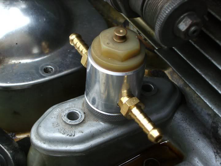
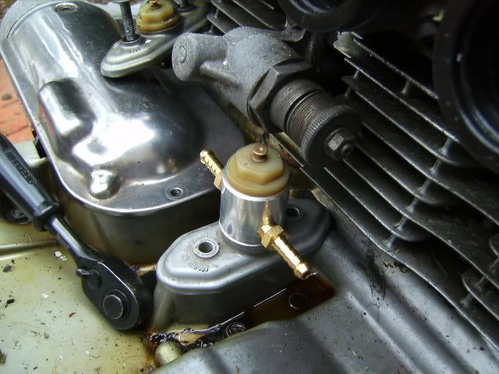
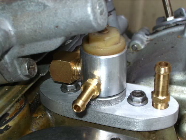
Here you go guys, Tom (Isleoman) asked me to make him an adapter for his top end oiler kit that allows him to retain his OEM pressure switch and GS1150 oil temp sender, so today I designed and machined up this adapter, that I call, "The Hydrant", ha ha!
Installation is a breeze, and can probably be installed with everything in place. If you can remove your oil pressure switch, (and loosen the two 10mm hex head screws) then you can install my adapter in just a few minutes.
It's a one piece item that threads into the oil pressure switch plate, (It'll work in most GS bikes from the 8 valve GS750 thru to the 16 valve 1150) with a knurled threaded ring to secure it in any position, and directs all of the oil flow up to your oil lines.
I'd promised to take the wife to the movies so didn't have time to go shopping for some nice NPT-to-AN hose fittings, so for the purpose of these pics I just threaded it for 1/8" NPT barbed fittings.
If anyone would like one, the price is $50.00 to GSR members, plus $20.00 airmail to your door. Cheers, Terry.
Comment
-
Nice solution
I guess you have been continuing to think about this problem and you really went "out of the box" for this. Even though it is taller, it looks cleaner than some of the previous solutions (although your other block was also clean).
OK just to be clear, you have posted this under a "Top End oiler" thread, but you say
So I'm confused or maybe you were just in a hurry for your explaination. A top end oiler for a 1100/1150 at least directs a portion of the flow after the OEM pressure switch to the cams, it also allows "parallel" flow to the transmission and engine gallaries.and directs all of the oil flow up to your oil lines.
At least according to your quote above, if you capture all of the flow and route it to the cams (both NTP fittings are outputs), the engine will starve for oil although the cams will be nicely lubricated. I dont really understand how a 8V motor would have any different top end oiler requirements than the 1100/1150 (assuming the opening are avaliable at the cams), so it woudl seem to suffer the same problem.
I can see how capturing all the flow is a requirement for the 8V oil coolers, but you would need to return the flow back to the gallaries and I think both of your fittings are outputs. I know you dont want to return the oil filter cover (see my previous warnings on that one).
I dont want to come right out and say "it wont work", but I'm really confused from your description how this does works.
Please explain.
Posplayr
P.S. The more I think about it the more it sounds like you mistyped. You really are not capturing all of the flow and routing it out of the NTP fittings, but are also allowing flow to go back to the motor inside of the "Hydrant". Assuming this is the case, then your solution should work for 8V or 1100/1150 and for the 8V it can be used in conjunction with the oil cooler block as well.
P.S2 Looking at the picture more closely, it looks like the two NTP fittings feed oil out from the main oil flow from the oil pump before the pressure switch. It there is no additional porting, then this will starve the engine of oil. If there is additional porting, then that will further alter the behaviour of the pressure switch.
Comment
-
 terry
terry
Ha ha, yeah mate, I was in a hurry, and the battery in my camera went flat before I could take some pics of the bottom half of my adapter.
The portion that sits between the bottom of the plate and the crankcase is cross-drilled to allow oil flow fore and aft, but I've purposely used a small drilling (3mm) so that the bulk of the oil pressure hits the pressure switch. I've also machined the base for the pressure switch contact a little bit lower to reduce the spring tension, so less pressure is required to open the valve.
As the oil lines are quite small ID, they will work as a "reducer" slowing the flow of oil through the lines, and allowing more oil to flow back into the galleries. I did think about another take off from the "Hydrant" with a return line back thru the switch plate, (maybe using a "T" like you've done) or making a whole new base plate, but I wanted to keep it simple, and anyway, I don't think it's necessary.
The reason I built the adapter was to capture more oil, your solution is nice and simple, but the problem that I see is that yours is positioned directly above a "drain" into your transmission, so with the restriction of the small ID lines and not much pressure pushing the oil up there at that point, I imagine that most of the oil will flow into the drain below your adapter with not much oil actually moving thru your lines.
Once my camera battery is fully charged, I'll post a couple more pics. Cheers, Terry.
Comment
-
 terry
terry
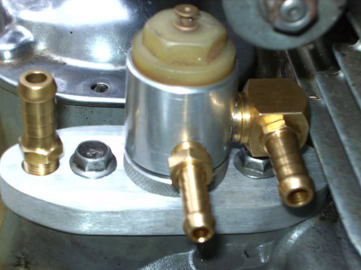
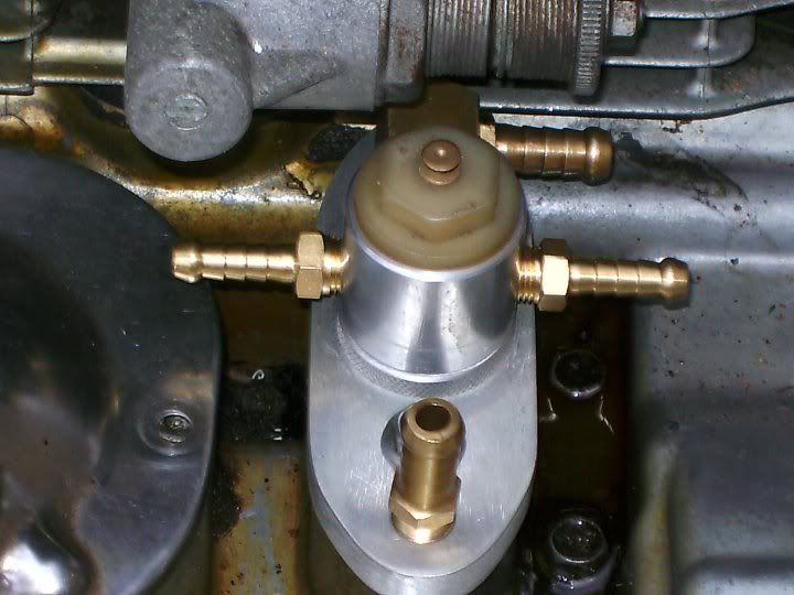
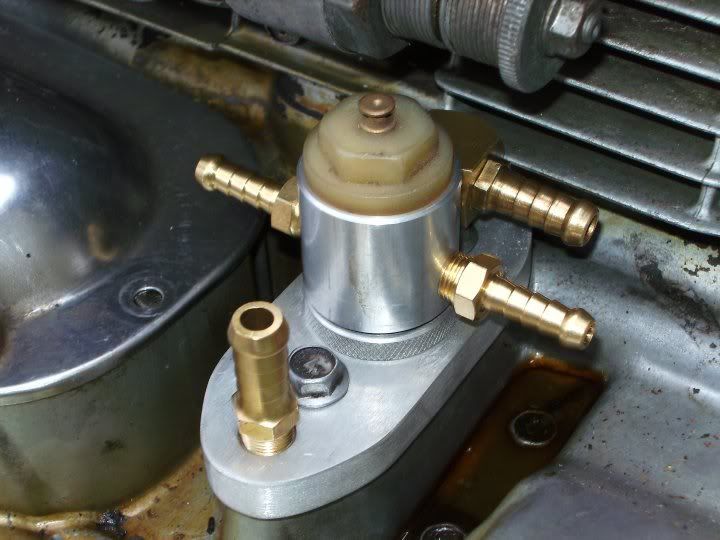
Here's some pics of another one I made today, it's a combined oil cooler/top end oiler adapter, as I figure the 8 valve GS guys who are modifying their bikes for performance would benefit from both a cooler and a top end oiler, and the 16 valve guys who aren't keen on oil lines running close to hot headers might like it too.
Sadly I ran out of time today, but next weekend I'll make up a "kit" with some nice braided lines for my GS1000 engine, and I'll post some pics. Cheers, Terry.
Comment
-
 TheCafeKid
Hey Terry, I installed my cooler, and thanks on that adaptor man its beautilicious and BTW, they buff up shinier than the top of the Chrysler building. But, my oil pressure light wont shut off at all. I know i have correct pressure cos i am using a RenoBruce gauge, but is there anything i can do to correct its sense that its low on pressure? Right now i simply disconnected it so the light would go out. Any suggestions?? Thanks
TCK
Comment
-
 terry
terry
G'Day mate, thanks for that, I'm glad you like it! Was it you who posted the pics of the polished adapter in another thread? It looks fantastic, I might use those pics (if you don't mind, of course) when I put one on EBay soon.
I haven't had a problem like you've described before, but try this: add another "O" ring (or a thicker one) to the existing one on the oil pressure switch, this will slightly raise the switch and reduce the pressure on the spring in the switch, and should cure the problem, with no oil leaks.
One other thought: One guy I sold an adapter to had a problem with the oil pressure light flickering, but as he was running a big cooler he added another pint of oil, and his light stopped flickering. just a thought..... Cheers, Terry.
Comment
-
 TheCafeKid
No problem mate! use the pics if you like, tho the polishing credit will have to go to Steve from the board here. He has a habit of polishing everything that will take a shine, a good habit of courseOriginally posted by terry View PostG'Day mate, thanks for that, I'm glad you like it! Was it you who posted the pics of the polished adapter in another thread? It looks fantastic, I might use those pics (if you don't mind, of course) when I put one on EBay soon.
I haven't had a problem like you've described before, but try this: add another "O" ring (or a thicker one) to the existing one on the oil pressure switch, this will slightly raise the switch and reduce the pressure on the spring in the switch, and should cure the problem, with no oil leaks.
One other thought: One guy I sold an adapter to had a problem with the oil pressure light flickering, but as he was running a big cooler he added another pint of oil, and his light stopped flickering. just a thought..... Cheers, Terry. I will give that oring a shot. Ive actually had my oil system OVER full when i first installed the cooler system, and of course it found its way out of every weak gasket it could untill the volume came down to a reasonable level
 Thankfully it was simple gaskets like the half moon plugs, and the cam tensioner gasket. No biggie. So, that wouldnt work for me...lol. I am kinda thinking maybe the plate on the end of the pressure switch is hanging up in the bore you make for it, and the extra ring may get it away from the spot it hangs up in. My problem is different from most, as most ive read have a problem with it coming on at idle, mine stays on all the time, so this is what leads me to believe its hanging up. Thanks again Terry, terrific product, only thing I would suggest, and I guess this onus could be put on the buyer, is maybe to include stainless bolts for us guys who want to shine em up. We gave a shine to the included bolts and they were nice and shiney till the first time they got wet, then they flash rusted. Ahh well....cosmetics is cosmetics. I know my bike is much happier with her nice temperature moderated oil tho!!
TCK
Comment
-
 terry
terry
No worries mate, I was providing stainless screws for years, but my local supplier shut up shop so I've been at the mercy of my hardware store, but I'll make an effort to only supply stainless from now on, thanks for your feedback! Cheers, Terry.
Comment
-
Forum LongTimerGSResource Superstar
Past Site Supporter
Super Site Supporter- Mar 2006
- 35620
- Torrance, CA
The oil pressure switch is a simple plunger that makes a ground path when the plunger is contacting metal. On a stock bike the plunger contacts the top of the oil port in the engine; when oil is burbling up out of the port, it pushes the plunger out of the way which disrupts the ground path, causing the light to go out.
For your bike Josh, the plunger must be contacting metal all the time which is keeping the switch from turning off. You might want to pull the adapter plate off and take a close look at the plunger to see if it's hanging up somewhere - perhaps on the side of the plunger.
Good luck.Last edited by Nessism; 07-27-2008, 07:18 PM.Ed
To measure is to know.
Mikuni O-ring Kits For Sale...https://www.thegsresources.com/_foru...ts#post1703182
Top Newbie Mistakes thread...http://www.thegsresources.com/_forum...d.php?t=171846
Carb rebuild tutorial...https://gsarchive.bwringer.com/mtsac...d_Tutorial.pdf
KZ750E Rebuild Thread...http://www.thegsresources.com/_forum...0-Resurrection
Comment
-
Top end oiler
I want to reiterate a couple of points that I thought were clear from the first few posts to this thread.
On both the 8V and 1100/1150 motors:
a.) the oil pump pushes oil through the filter and then to a pressure switch under the carbs.
b.) The dynamic pressure of the oil coming out of this center port directly under the rear cover (the same force of air you feel pushing your hand when you hold it outside of the car at 55 mph) pushes the plate on the switch, opening a contact (in the switch) and the light goes out on your dash. In other words, it is not actually static pressure under the plate, but rather the flow hitting the plate head on that makes the switch work.
The only way to retain the OEM operation is to keep the plate in the orifice hole. Terry has repositioned the switch plate and apparently modified the switch spring to get proper operation? Maybe he could explain it better.
c.) In the third post of this thread is shown the Suzuki manual for a GS1100 but it is virtually the same flow from this central orifice for the 8V motors. It was presented that all of the pressure under the cover is at the same pressure for a stock configuration, and so any opening (like the rear fitting I showed) to feed a top end oiler will supply oil to the cams and largly leave the primary flow undisteurbed.
However.....
d.) The concept of capturing all of the flow and routing it outside of the engine (i.e. to the top end oiler) would completely upset the primary oil flow (exception: unless it was returned back to the plate to continue the normal flow) Terry 8V combo adapter apparently does show this return.
So for a simple Top End Oiler install (8V or 1100/1150) without trying to run additional 8V plumbing for a cooler, it would be a bad mistake to capture all of the oil flow and try and push it to the cams.
Capturing all of the oil flow is accomplished by running a tube down the center of the adapter. If someone were to install this tube with a top end oiler they would be starving the motor according to an analysis of the Suzuki provided engine description. See below.
Whoever designed a tube to capture all of the flow for a GS 8V or Gs1100/1150 top end oiler and route all the oil to the cams alone doesn't understand what they are doing or they plan on running a "dry sump" system (intended or not)

I would suggest doing "before and after adapter/oiler" pressure tests at the indicated position (VDO gauge) to make sure the pressure/flow has not been upset. The position is the recommended gauge position that RenoBruce puts his side gauges at.
Posplayr
Comment
-
Forum LongTimerGSResource Superstar
Past Site Supporter
Super Site Supporter- Mar 2006
- 35620
- Torrance, CA
If I understand right, Terry's Top-End Oiler adapter has a cross-drilled (3mm holes) extension piece that picks up the oil from the oil port in the engine. These holes allow oil to feed the transmission thus keep it from oil starving. My question is whether or not these holes, which will bleed off oil flow, will feed enough oil up through the oil pressure switch to turn off the light at idle.
One one of my early iterations in building an oil cooler adapter used an extension piece to pick up the oil that allowed some bleed off - adapter extension did not fit down tightly on the oil feed port. In the end there was enough oil bleed off so the oil pressure light would come on at idle. Making a new extension that cap 100% of the oil flow worked much better in terms of keeping the light off.Last edited by Nessism; 07-27-2008, 04:12 PM.Ed
To measure is to know.
Mikuni O-ring Kits For Sale...https://www.thegsresources.com/_foru...ts#post1703182
Top Newbie Mistakes thread...http://www.thegsresources.com/_forum...d.php?t=171846
Carb rebuild tutorial...https://gsarchive.bwringer.com/mtsac...d_Tutorial.pdf
KZ750E Rebuild Thread...http://www.thegsresources.com/_forum...0-Resurrection
Comment
-
Nessism
Terry would be the best to explain how his Top end oiler and his combo oiler cooler adapters work. From his description to me they are really two different animals although he seems to be treating them similarly.
I ran some numbers and I would be very concerned no matter what the cross drilling is using 3 mm holes on an top end oiler.
The cross drilling (which controls how much of the primary oil supply is being captured), there may or may not be any issues with oil supply on the combo unit, I don't know how it is modified internal. Here are some numbers for how many 3 mm cross drills would be required to support the total flow from the central orifice assuming it is 3/4" (I can't measure one at the moment)
It would take 20 cross drills to equal the area of the primary supply port. Hopefully he is not capturing as much as he thinks and has a loose fit on that neck
hole size (diameter) 3.00 3.00 mm
per hole area 7.07 7.07 mm^2
Tube cross drills 1.00 20.00
total area 14.14 282.74 mm^2
equivalent port size 4.24 18.97 mm
required size 18.75 mm
hole area 276.12 mm^2
Any way below is my suggestion to modify Terry's Top end oiler adapter to retain exact function of the OEM pressure switch, provide a supply of oil to the top end oiler after the pressure switch and leave the primary flow of oil to the galleries unaffected save for the small supply being allowed to escape to the cams.
The trick here is to retain the exact same configuration of the pressure switch plate at the end of the shaft. It has to be in the primary port so that the flow can push on it. At the same time in order to make enough room to put oiler ports or other sensor ports, we need to raise the screw in sensor device. An extension on the shaft will leave the pressure plate in the original position but allow the room required for other port take-offs. I'm going to prototype this just waiting on some parts. It will do exactly what my existing original solutions does, it will just give me the option to add additional sensor ports plus clean up the look a little.
If there was a legacy 8V cooler adapter someone had that had proper operation for the pressure switch this adapter could be used in conjunction.
Posplayr

The only question about this solution is how stiff the shaft extension needs to be or if it needs to be supported by a bearing surface. I dont think so.
I think there is some misunderstanding going on about the pressure switch and how it operates based on oil flow. While there will be pressure in the system if there is flow from the pump, putting teh sensor into a pressurized volume will not activate it. The pressure switch plate (at the end of the shaft) requires flow of sufficent flow rate ( alternatively dynamic pressure) to push the plate. There has to be flow against the plate not just local pressure to depress the pressure switch. Thsi is why TCK switch doesnt work, the plate has been pulled out of the primary port and so it will take a huge flow volume to get enough flow in the open area to push against the switch plate. Depending upon the distances it may not be possible.Last edited by posplayr; 07-27-2008, 05:03 PM.
Comment
-
 terry
terry
Has any one here got a WARDS Vortex adapter on their bike? The WARDS Vortex adapter uses a pickup tube just like mine, but I don't know if it's cross drilled, like mine is.
As far as the possibility of oil starvation concerns go, the 3mm holes in my pickup tube are roughly 3 times the ID of most top end oiler hoses, so I doubt if that's really a concern.
The new top end oiler/oil cooler adapter will work fine on all GS Suzuki's from the GS750 to the 1150. Cheers, Terry.
Comment
.png)
Comment