.png "Powered by vBulletin")
Originally posted by gsinmaine
View Post
-
 Guest repliedAlmost certainly the R/R is charging too hot. It's an easy fix with a used $40 R/R.
 -
Guest repliedR/R problem or??
Hello all. I am a newbie to this site and want to say what a great site this is. I never realized that there were all that many followers of the GS line. I personally have a 83 GS1100 Laverne with all the correct period Vetter accessories. Anyway, on the to question. Laverne is charging at 17V at about 3.5K rpm. I cleaned all the plugs, pigtails and so on and have grounded the black wire off the R/R direct to the battery to no avail. She is still charging hard. Drops to around 14 or even 13. 5 at an idle. Needless to say, my one year old battery is as dry as a popcorn fart. ( or just about anyway) I am betting on the regulator going south. Is this a safe assumption? I know on a 70 Ford high charging is a stuck regulator that was corrected by some well placed sharp raps with a screwdriver handle on the regulator. This not being Ford, and by reading all this high tech. talk, I am sure someone will be able to narrow this down. Otherwise, the bike runs like new. 17K on the clock. Best bike I have ever owned, except for the seat. Gets kinda hard around the 4th hour. Other than this, it is fast enough, smooth enough, economical (both at the pumps and at the tax collectors office) and just an all around fine machine. Great site!! GSer's rock on......Leave a comment:
-
Guest repliedOk. I think i'm getting it....sometimes i'm not to bright lol The ground I have been using is on the side plate next to the starter relay. I didn't think it would make a difference because I have a ground wire there that goes back to the battery.
I replaced the fuse box last summer. I had the whole harness out and cleaned/replaced all the connections. I actually took regular vaseline and dipped all the connectors before I plugged them in. They still have the vaseline in them even through the heat of the summer.Leave a comment:
-
Roy
Ok GoodOriginally posted by dennis roy View Post
As described below. the R/R (-) wants to be attached to the frame at the closest point possible (i.e. shortest wire). When I say frame I mean frame and not the side plate that everything mounts to.Originally posted by dennis roy View Post
2.) Run a ground with as short a wire as is practical from the same R/R mount to the frame. I used the rear airbox screw hole.
If the connections to your fuse box are good enough then doing this will work. Only as a last resort would I completely go around the fuse box with a separate in line fuse. Depending upon your fuse box style, you can dip all the connections is an acid like navel jelly wash it out and solder the connections to keep out any corrosion.Originally posted by dennis roy View Post
Hopefully if you get these connections squared away you will charge up to 14.5 volts at 3K RPM and be close to 13V at idle.
The difference is the connections.
PosLeave a comment:
-
Guest repliedI did put a fuse in line from the r/r to the batt. So I should be able to attach the r/r- to the mounting bolt like you mentioned, then I could go from that to the ground wire behind the engine. I have used that to ground my starter. It has a large cable that goes to the neg. batt. terminal. I was actually wondering if I should just bring the + from the r/r back to the original wire it was attached to.Leave a comment:
-
Connections matter
The charging system deals with relatively high currents (8 to 15 amp as per your measurements) and relatively small voltage ranges that provide good operation and battery charging (12.8-15V).
In addition there are some limitations of the devices (R/R without differential voltage sensing ) that are being used, so getting the connections right is pretty critical.
When you do that the R/R output voltage is higher than the controlled voltage level (e.g. 14.5V ) and the regulator will get hot trying to shunt stator power. This is not a good idea to do.Originally posted by dennis roy View Post
Also because you wired the R/R output directly to the Batt (+) you may have subverted your fusing. Clearly the R/R to battery connection is not fused.
With 15 amps, that means that the stator is good and the diode bridge in the R/R is functioning.Originally posted by dennis roy View Post
Since you can pull the voltage down from 15.0V to 12.0V the regulator is functioning.
Hate so say, it but the operation is faulty because (it would seem) your selection of connections are not very good.
I can not access what this means.Originally posted by dennis roy View Post
My suggestion would be:
1.) Attach the R/R (-) directly to the R/R mounting screw
2.) Run a ground with as short a wire as is practical from the same R/R mount to the frame. I used the rear airbox screw hole.
3.) Run a single wire from the same R/R mounting bolt to the negative side of the battery.
4.) Run the R/R (+) red wire to the red wire on your harness where your old R/R connected.
That will not be the best you could do, but generally that should solve all problems. The schematic at the top of the Ground Loop thread shows the connections in solid black.

PosLast edited by posplayr; 03-26-2009, 01:18 PM.Leave a comment:
-
Guest repliedYes that's the style. I attached the + to the terminal on the same terminal on the starter relay that goes to the + batt. terminal. The ground goes to the bolt on the starter relay and the other bolt on the relay goes to the - batt. terminal.
I just checked things out a bit. When I remove the + wire from the r/r to the batt. it tests at almost 15v. When I connect it back to the battery it reads just over 12v and never goes much over 13 at 5000rpm. I test amps from the r/r and it shows 16 amps at 5000rpm and about 8 amps at idle. checked all connections and grounds all are good.Last edited by Guest; 03-26-2009, 12:37 PM.Leave a comment:
-
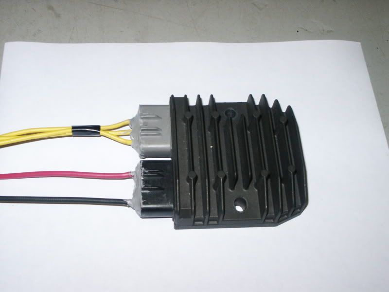
Dennis, what R/R are you using, a FET style like this?Originally posted by dennis roy View Post
you would connect each of the three yellows to the three wires coming out of the stator .which to which does not matter.
note the position of the red and black and yellow wires...
Originally posted by posplayrLast edited by rustybronco; 03-26-2009, 08:17 AM.Leave a comment:
-
Guest repliedok...so my next stupid question before i go out there and rip it all apart. does it matter which wire from the stator goes to what plug on the r/r? Other than the + or - plugs that is.Leave a comment:
-
Measurements
Next I would recommend that the R/R is well grounded to the frame and check what the voltages are between the following
Volts from R/R (-) to Batt (-)
Volts from R/R (+) to Batt (+)
Volts from Batt (+) to Batt (-)
get an idea where you stand at both idle (1200 rpm) and 4KRPM.
What R/R are you using on what Bike?
If you are only pulling 6 amps, with lights on it woudl seem like the R/R (-) ground is not supporting the return current required.
PosLeave a comment:
-
Guest repliedOK just did the no-load test and my stator is pushing more than 80 volts across all leads. The amps out of the r/r is about 6 amps steady with break lights, directional, and high beam including my driving lights or without anything at all.Leave a comment:
-
Did you so the stator page tests
Un plug the stator and do that portion of the test.
U need a VOM.
PosLeave a comment:
-
Guest repliedWell now i'm confused. I replaced the r/r today. It charges at about 11 volts at idle and never gets over 12.5 when its revved. Stator bad maybe?Leave a comment:
-
Guest repliedit's an '82 850glz. guages off an '84 1100e, hard bags off an '84 1100gk, forward controls, saddle style seat. i'm gonna try to fit the tank off the gk also so i don't have to stop so often for gas.Leave a comment:
-
GS Charging System Design Overview
The attached figure shows a comparison of the performance to be expected from a FET based shunt R/R (i.e. FH012AA) and a more conventional SCR based shunt R/R when used in conjunction with a GS charging system.
The valves are approximate based on the recent measurements I made on my GS1100ED.

Supply and Demand Curves
First what is important to note is the load demand curve (the red curve). At idle (1250 RPM) the demand curve requires about 10 amps. As RPM increases the demand only goes up about 25% to say 12.5 amps at 6000 RPM. The curves are approximate but are based on measurements made with a DC current probe on the R/R red output wire.
The large initial demand is due to lights and ignitor which are almost constant load, and a speed dependent portion which is most likely the ignition coils. So the generator needs to put out about 10-13 amps and no more and no less.
In the lower pair of curves we see the approximate regulation duty cycles (not to scale) for the two R/R types and when they begin regulation. The FET starts to regulate at a lower RPM because of the lower drops in the R/R allow for a higher voltage to go to the battery. As the output voltage rises , the FET regulator hits 14.5V at a lower RPM and so regulation starts at a lower RPM. SCR R/R regulation is probably delayed till something closer to 3K RPM. There are approximate values YMMV.
Since a permanent magnet generator should have an output voltage which is proportional to RPM, and since we see only a relatively small change in the control duty cycle, (50% to a maximum of 45%), we have to assume that something is limiting the generator output as the R/R only seems to be doing some marginal trimming.
We have to assume that it is a saturation effects in the stator magnetic feild that are limiting the power output at higher RPM. In my earlier comments about “system design elegance”, this is what I was referring to. The stator was designed with the ability to supply only so much current before the magnetic field material saturate. This effectively caps the stator output power even though RPM keeps rising. See the link below fro an explaination of magnetic staturation.
Saturation
The principle at operation here is that the generator supply curve was designed to closely match the demand curve so that the R/R doesn’t have to dump/disapate as much current. The R/R’s responsibility lies primarily with rectification and only does a partial job of regulation.
see quote below from Post #103 in this thread
Voltage RegulationI am drawn back to a statement that a fellow GS member (I won't guess who it was because I don't remember) made here a while back about the charging system. The statement was something to the effect that "the charging system is not intended to charge the battery". I'm pretty sure that he had heard that conclusion from someone more knowledgeable about the charging as the statement was unqualified or elaborated on. So I'll guess further as to the meaning..
The system level elegance that I speak of is to take the simplest generator design and match it's output to the demand curve for the motorcycle as a function of RPM. Using this approach, the system can be designed simply and is almost fool proof as even without any voltage controls the generator and load are matched. OK so you can't quite do that so you need to have some regulation because the battery is relatively intolerant of over charging. Some form of regulation is required. Unfortunately for Suzuki, the elegance of the systems engineering did not translate into a well executed R/R design. Given the recent heating of my Electrosport it is not a whole lot better. Honda did a better job on their R/R.
The upper curves show what the R/R outputs would be with no regulation. We can see that due to the lower drops in the FET regulator, the R/R produces a higher voltage at idle than the quiescent battery voltage (12.8V). The SCR regulator may or may not be below 12.8 at idle but it is certainly below where the FET R/R would be operating.
Power Dissipation:
I had previously measured voltage drops for the SCR R/R at approx 3.4V total and about 1V total for the FH012AA. So the FET regulator is dissipating about 1/3 as much power as the SCR based R/R. As has been recognized (back tracking on some of my earlier comments) the power not dissipated in the R/R will be dissipated in the stator. However since the stator is already dissipating close to 200W (12.5*14.5= 181W) adding an additional 25 watts is only about a 10% increase. In addition the stator is better equipped to dissipate power albeit through 250 degF hot engine oil. On the other hand reducing power dissipation in the R/R to 1/3 should yield a significant improvement in reliability due to reduction in component junction temperatures.
One still might worry that the FET based R/R is stressing the stator too much due to the hard shorting (near zero voltage drop of the FET). However refereeing back to the magnetic saturation characteristics, the stator is just incapable of increasing the current flow any more than it already is so the likely effect is negligible.
Summary
The revelation here is that the overall operation of stator- R/R-Load system is to match the generator supply curve as close as possible to the loads demand curve. In addition the supply curve should always exceed the demand curve. There are some additional conclusions we can draw:
It is hard to imagine that with the magnetic core saturating as is apparent, that rewinding a stator will ever yield an additional 20% more power. The power output of the generator was designed to be limited so that the shunt control was not over whelmed at high RPM.
The R/Rs’ primary job is to rectify and closed loop operation is actually very limited. The FET regulator supports the role of the R/R in that for the GS, it allows the generator output voltage to exceed the battery voltage at a lower RPM, and it dissipates less power resulting in a more robust solution due to lower junction temperatures.
In contrast the SCR based regulator is at best marginal at idle and a typical GS actually discharges at idle using the SCR R/R. In addition the SCR R/R must dissipate 3 times the heat of the FET design in a very similar package to the FET design. The FH0012AA is actually larger than the typical SCR design.
Conclusion:
So is the FET worth it? Given the limited role the SCR R/R has, it actually does it’s job fairly poorly. R/R’s get hot and can fail and may not charge at low RPM. These problems largely go away with the FET design. The SCR R/R will work, albeit marginally. The FET design does a better job, and in the world of “GS charging compromise”, this really is a break through technology.
PosLast edited by posplayr; 03-20-2009, 08:51 PM.Leave a comment:
.png)
Leave a comment: