Announcement

Collapse
No announcement yet.

1981 GS450E Rebuild

Collapse
X
 
  • Filter
  • Time
  • Show
Clear All
new posts

  • pete
    replied
    Hahaha 8 gears? Right on! That'll get the little 450 humming

    Andre, I haven't seen those before although I wasn't looking either... I've become quite attached to my 6 digit gear position indicator

    However, looking at the auction details shows it's only for 5 speed bikes, N through 5, whereas my 450 has 6 and the Acewell has a neutral light.

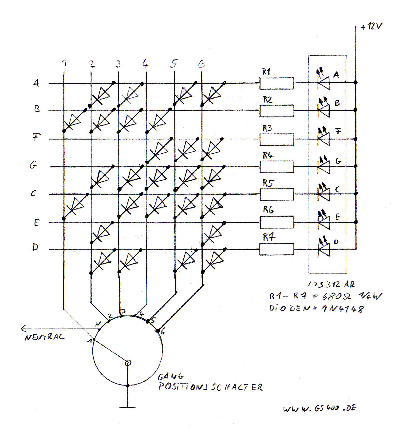
    This is one I have seen though that I did initially contemplate early on:


    Even though it's in German the circuit layout etc. is easy to understand and it would be very simple to make.

    Leave a comment:


  • Matchless
    Guest replied
    Originally posted by Suzuki_Don View Post
    WOW 8 gears!!
    Imagine that at the next bike meeting! Its like having a speedo marked to 300km/h! Some will even believe it.

    Leave a comment:


  • Suzuki_Don
    Guest replied
    WOW 8 gears!!

    Leave a comment:


  • Matchless
    Guest replied
    Originally posted by Englishman View Post
    ...and then have looked further at how they are installed, maybe not.

    Whoops! Sorry linked to wrong one!

    Here is the one I meant to link to, uses switched power and then a ground from the gear position indicator will light the related gear number.

    Leave a comment:


  • Englishman
    Guest replied
    ...and then have looked further at how they are installed, maybe not.

    Leave a comment:


  • Englishman
    Guest replied
    Originally posted by Matchless View Post
    Oh I like the look of that....... I may just risk the $26

    Mark

    Leave a comment:


  • Matchless
    Guest replied
    Pete,
    Have you seen these yet?
    http://www.ebay.com/itm/Red-Universal-Digital-Gear-Indicator-for-Motorcycle-New-/110766688272?pt=Motorcycles_Parts_Accessories&hash =item19ca358810&vxp=mtr

    Edit: This is the one I meant to post! http://www.ebay.com/itm/New-Digital-...016b6b&vxp=mtr

    Sorry!
    Last edited by Guest; 03-29-2012, 04:14 PM. Reason: Updated link

    Leave a comment:


  • pete
    replied
    Ok, so here's the plan on the whiteboard:


    The bottom drawing there is based on the existing bracket for the original gauges and will be made out of the 2.5mm alu.

    You can see where the Acewell will mount on the right, the rectangular cutout at the bottom is for the gear position indicator, and the round hole is where I expect I'll need to put the voltage monitor and the two wires will need to exit there.

    The top drawing will form a box that will butt up against the side of the Acewell and you can see the cutout for the gear position indicator and the hole for the voltage monitor.

    I still have plenty of the perspex here from the fly screen so I'm thinking it would look good if I laid a sheet of perspex over the entire boxed area there.

    I'll have to see how things pan out.

    Here's the bottom bracket drawn out on the 2.5mm alu. ready to cut out:


    I ordered a bunch of stainless steel nuts and bolts today as well as some alu. tubing. The plan is to make standoffs with the tubing to support the box and gear position indicator and the bolts will go through the tubing to bolt it to the bottom bracket. I hope that makes some sense...

    If I do Andre's idea of a switch, that also leaves plenty of room for it.

    Leave a comment:


  • pete
    replied
    Originally posted by Matchless View Post
    Pete, that looks quite nice! You could even wire the link to a hidden miniature push-button switch to check the battery voltage when she is not running!
    I have bought a blue digital voltmeter, but it was too big, then a red digital one which is smaller, but is hard to read in the light, so my trusty old car analogue meter will stay!

    You are really doing fantastic work on your bike!
    Now that's a damn fine idea Andre! Didn't even think of that! I reckon you're onto something there... might have to give that a go... just a momentary switch I can hold while I flick the ignition on should do it I think, then it can go back to a voltage monitor...

    And thanks, I'm lovin' working on it and I finally feel like it's almost what I'd consider complete

    If I can get this bracket done, sort the jetting out, and get a rear carry rack made up to replicate the genuine sports one, then she'll be "done"... finally!

    Originally posted by Englishman View Post
    Are you going to incorporate the digital gear position LED Pete ?
    Yup that's the plan Mark, got the sum total of two photos uploading now so will update shortly with the diagrams and what the plan is...

    Leave a comment:


  • Englishman
    Guest replied
    Originally posted by pete View Post
    I just bought this on eBay tonight:

    Fully rubber wrapped for waterproofing and shock resistance. Auto Mode Switching. Its annoying when your battery goes flat without warning. Integrated tri colour (Red, Green, Yellow) 10mm LED and microprocessor assembly - indicates SIX different conditions.


    Be here in a couple of weeks I guess, which should give me time to get the bracket organised.

    I've got the basic layout on the whiteboard, just need to translate that into aluminium and I think I'll spray it with the satin black like I did the battery box too.
    Are you going to incorporate the digital gear position LED Pete ?

    Leave a comment:


  • Matchless
    Guest replied
    Originally posted by pete View Post
    I just bought this on eBay tonight:

    Fully rubber wrapped for waterproofing and shock resistance. Auto Mode Switching. Its annoying when your battery goes flat without warning. Integrated tri colour (Red, Green, Yellow) 10mm LED and microprocessor assembly - indicates SIX different conditions.


    Be here in a couple of weeks I guess, which should give me time to get the bracket organised.

    I've got the basic layout on the whiteboard, just need to translate that into aluminium and I think I'll spray it with the satin black like I did the battery box too.
    Pete, that looks quite nice! You could even wire the link to a hidden miniature push-button switch to check the battery voltage when she is not running!
    I have bought a blue digital voltmeter, but it was too big, then a red digital one which is smaller, but is hard to read in the light, so my trusty old car analogue meter will stay!

    You are really doing fantastic work on your bike!

    Leave a comment:


  • pete
    replied
    I just bought this on eBay tonight:

    Fully rubber wrapped for waterproofing and shock resistance. Auto Mode Switching. Its annoying when your battery goes flat without warning. Integrated tri colour (Red, Green, Yellow) 10mm LED and microprocessor assembly - indicates SIX different conditions.


    Be here in a couple of weeks I guess, which should give me time to get the bracket organised.

    I've got the basic layout on the whiteboard, just need to translate that into aluminium and I think I'll spray it with the satin black like I did the battery box too.

    Leave a comment:


  • pete
    replied
    Originally posted by deven5498 View Post
    Very nice!!! Can tell you have some time into that. Good catch on the male bullet hot lead. I have done that before.
    Thanks mate! Yeah plenty of time in it... probably too much again but at least it works

    And yes, was very glad I hadn't put the fuse in the holder when I let it go and heard the tink of the bullet hitting metal...

    Originally posted by Englishman View Post
    Nice work there Pete. From the pics I can't see where you installed the spedo magnet ?

    Mark
    Cheers Mark, it's a magnetic bolt replacing one of the front disc bolts, first pic in post #2194, here:


    You can just make it out as a slightly different looking bolt in front of the fork leg there. Sorry but the bike is filthy and that caliper paint is shocking... can't believe how bad that turned out!

    The best measurement I can get is it runs about 5mm from the sensor which is probably close to ideal.

    Originally posted by Big Rich View Post
    Good work Pete. Glad to see you have it wired up and running properly. I've been thinking about a voltmeter for mine as well.........so hurry up so I can steal your idea!
    Cheers Rich! Yeah very happy with how she runs, I was expecting tacho dramas like a lot of others have but I think by just putting the resistor in straight away helped that.

    As for the voltage monitor, I was going to build a 3 LED one as I have a lot of the components already, but it's going to get bulky again, so now I'm thinking one of these two:


    The first one's the simplest, but will take forever from the UK to get here.

    The second one won't be a difficult install at all and I'm thinking I can figure out how to hook up the unused warning light on the Acewell to turn on if the voltage ever goes over 15v as well.

    I'm struggling with the layout of the bracket for the Acewell and the rest but I can't really finalise it until I work out what I'm doing for a voltage monitor...

    And feel free to steal the idea too

    Leave a comment:


  • Big Rich
    Guest replied
    Good work Pete. Glad to see you have it wired up and running properly. I've been thinking about a voltmeter for mine as well.........so hurry up so I can steal your idea!

    Leave a comment:


  • Englishman
    Guest replied
    Nice work there Pete. From the pics I can't see where you installed the spedo magnet ?

    Mark

    Leave a comment:

Working...
X