Announcement

Collapse
No announcement yet.

here i go again.. project: 'too late to go back now'

Collapse
X
 
  • Filter
  • Time
  • Show
Clear All
new posts

    #16
    Lookin' good! Time to get the buffer and put a shine to them...or lots of elbow grease!

    Thanks for the update.


    Ed
    GS750TZ V&H/4-1, Progressive Shocks, Rebuilt MC/braided line, Tarozzi Stabilizer[Seq#2312]
    GS750TZ Parts Bike [Seq#6036]
    GSX-R750Y (Sold)

    my opinion shouldn't be taken as gospel or in any way that would lead you to believe otherwise (30Sep2021)

    Comment


      #17
      Here's a quick dremel polish with mothers compound.. Already looking sharp


      Comment


        #18
        Looks great!

        I also favour Mothers as a polishing compound, cheap, available anywhere and works well.

        Cheers - boingk

        Comment


          #19
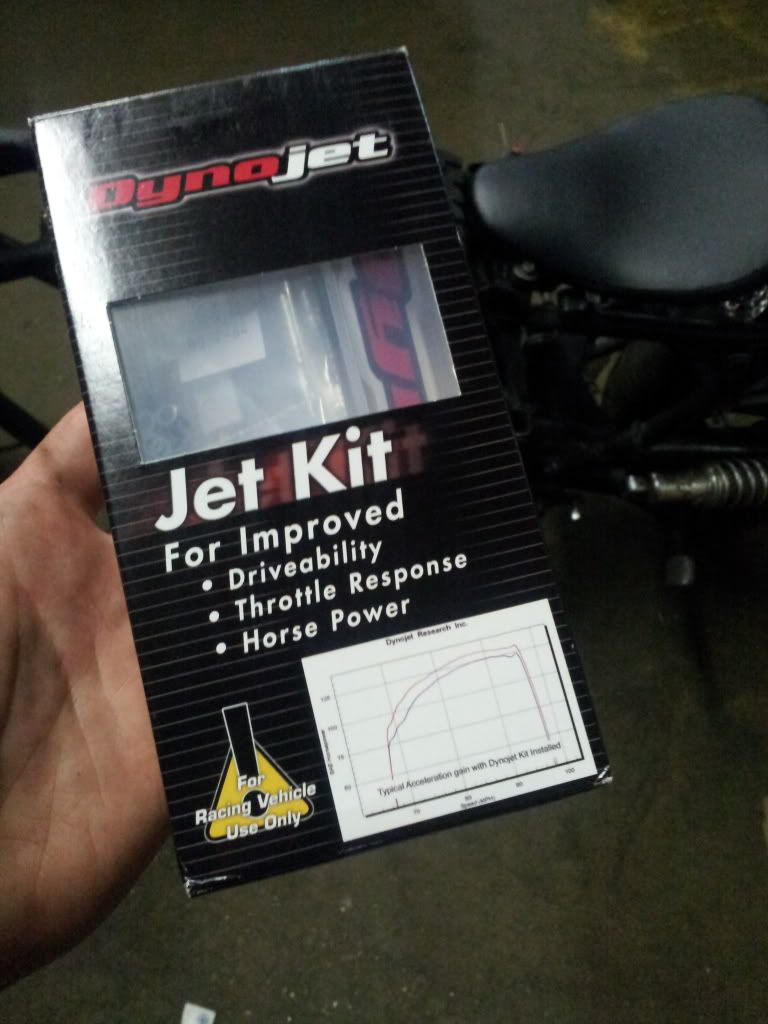
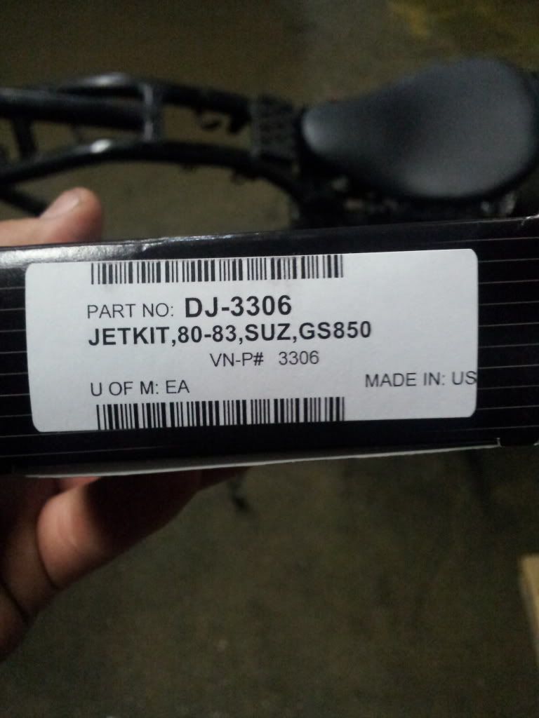
          Double bonus delivery today. I was home for lunch walking the dog as the mail man rode up... Seat, springs and jets! Time to get dirty soon


          Comment


            #20
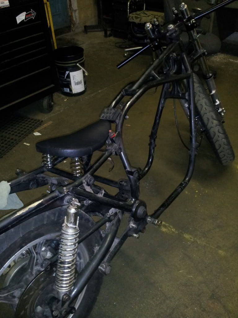
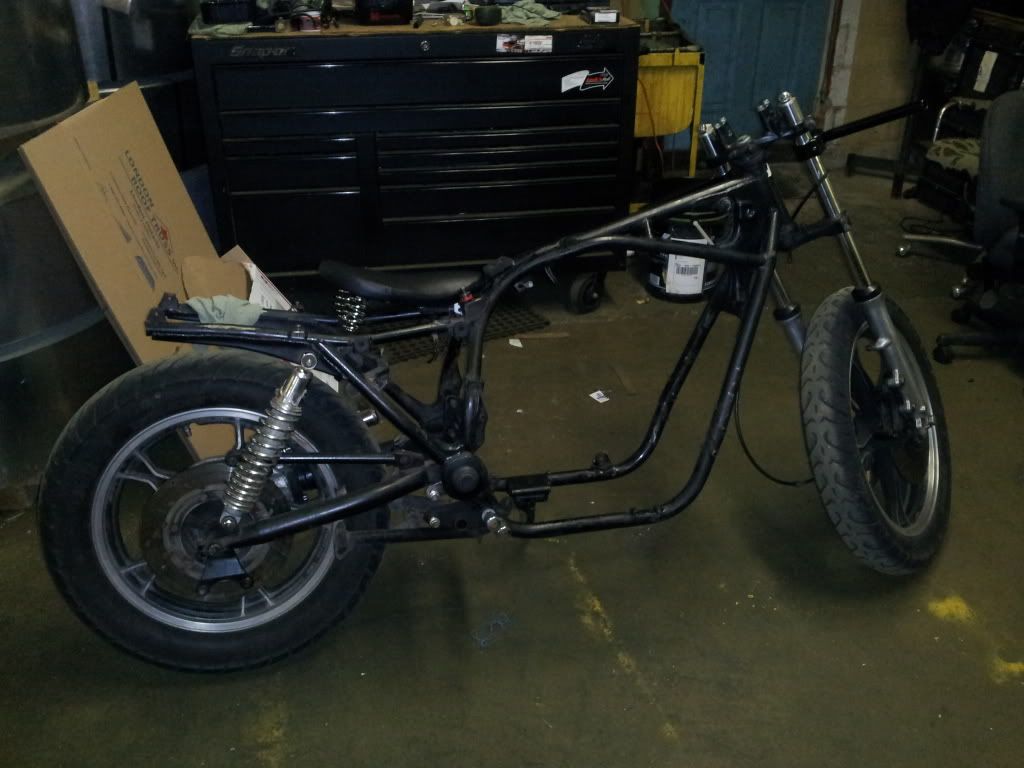
            Beginning some frame alterations. Tubed in the rear and removed some extra brackets.. Its a start.


            Last edited by Guest; 07-11-2013, 02:29 PM.

            Comment


              #21
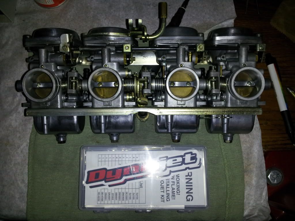
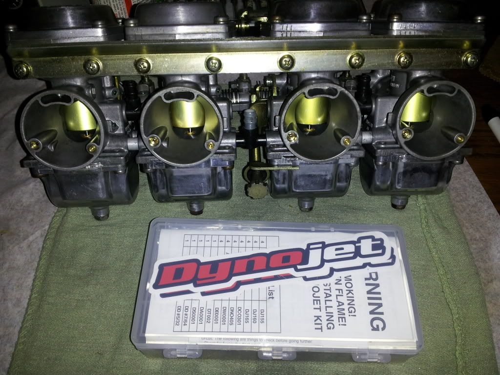
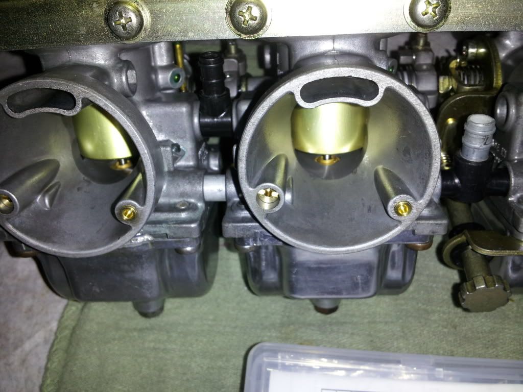
              Lucky me that the o ring sets showed up Friday evening! I was able to finish up the dynojet stage 3 and reassembled the carb set. Overall the dynojet kit was easy to install but took me a little while to determine the instructions. After you understand and know what and where the few new components go, things come together just fine.. Im hoping for positive results.


              Above: you can see the air correction plug on the right side, simply glued into the port and gently tapped to seat. Left side is my new main air jet.. Bike came with a 200 size jet! My rebuild kits came with 2 options; 180 or 190.. No 200?! I decided to install the 190 size and go from there


              I began looking at the motor on Friday morning and removed the valve cover to prepare it. Ill be getting into the valves soon.. Taking a quick glance into the exhaust ports and glancing at the plugs for a first time, i noticed cylinder 4 was a wet plug and exhaust was wetter then i would have liked. I also noticed the number 4 carb had some carbon build up in it but very little. . 1,2 & 3, were all in good condition but looking a little grey on the electrodes.. Possibly a little lean?? I quickly checked the intake valve clearance on number 4,, from a bunch of angles but my thinest shim would not go.. Maybe intake was stuck open a hair?? Ill check more into this Monday.. i pulled one of the intake boots from the motor to see the o ring was cracked and needing replace. Luckily i got those with my o rings on the Friday order also! I feel the rest will suffer similar results
              Last edited by Guest; 07-13-2013, 11:23 PM.

              Comment


                #22
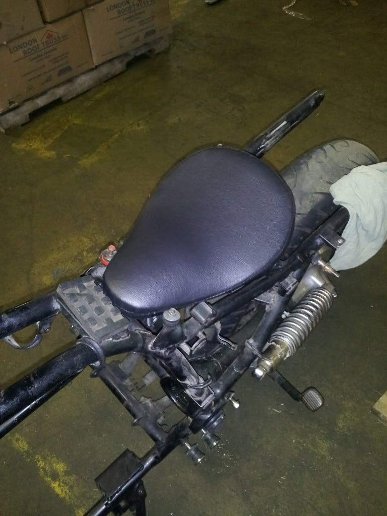
                Got my seat mounted.. Made some tabs and mounted them as seen. Nothing fancy but functional.


                Comment


                  #23
                  Pretty cool stuff! Thanks for the update.


                  Ed
                  GS750TZ V&H/4-1, Progressive Shocks, Rebuilt MC/braided line, Tarozzi Stabilizer[Seq#2312]
                  GS750TZ Parts Bike [Seq#6036]
                  GSX-R750Y (Sold)

                  my opinion shouldn't be taken as gospel or in any way that would lead you to believe otherwise (30Sep2021)

                  Comment


                    #24
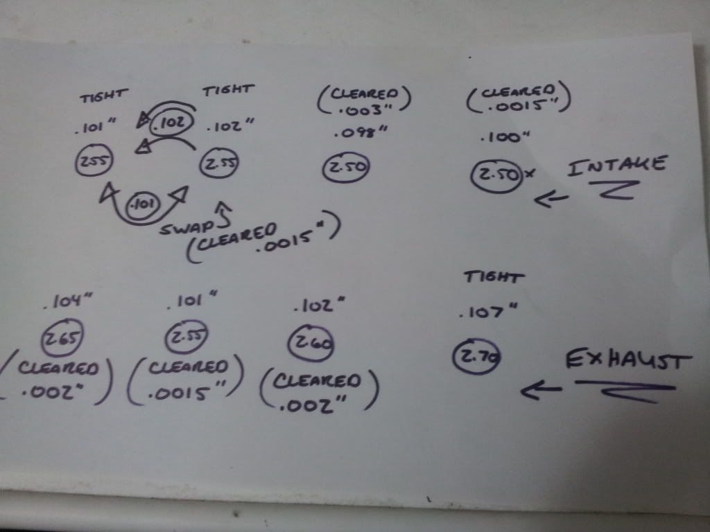
                    I spent some down time today playing with my engines valve clearances.. First of all take a look at this diagram below to see my results as i describe my situation..


                    The stamped given metric equivalent of each shim is noted in the pictured diagram above. 8 circles above indicate each valve shim, intake on top and exhaust at the bottom.. I also decided to reference each shim with an actual imperial measurement.. The given metric stamps varied from the actual size,, maybe due to wear?

                    First and second intake were shimmed with a similar stamped shim but differed by .001".. Because i couldn't achieve the clearance i wanted on the first 2 intake valves, i saw an opportunity to swap intake 1 and 2 shims. Doing so gave me .0015" clearance on the second intake but first intake remained tight.. Actually tighter then before..

                    The remainder of the valves were relatively between the specs of a minimum .001" and max .003" clearance, except for the last bottom right exhaust valve which still remains tight until i can acquire the thinner shim for the 2 remainders.. But i may just end up grinding the shim down to a useful size if i fail to turn up an inexpensive replacement.

                    Comment


                      #25
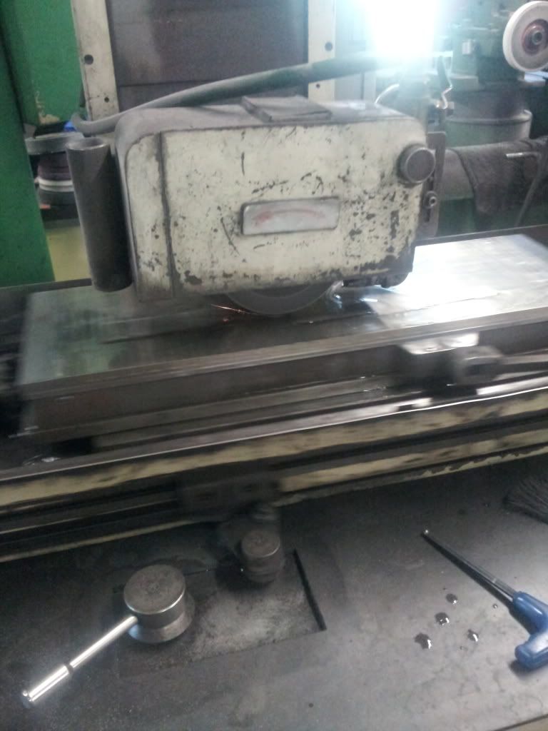
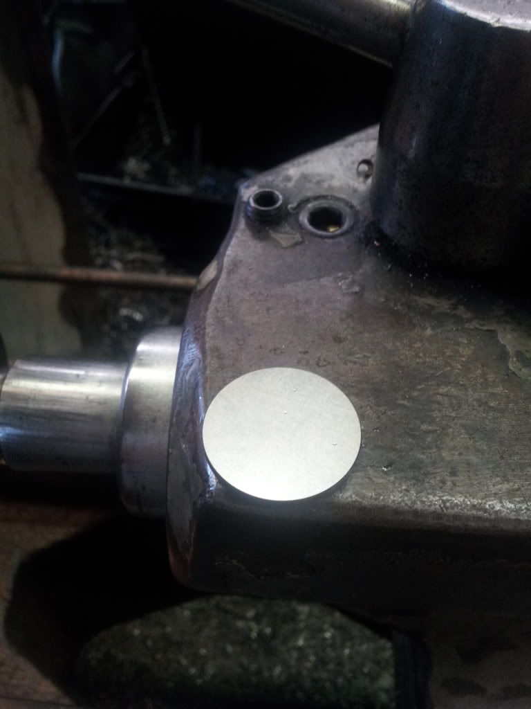
                      Call me lazy or call me crazy, but i found it really easy and convenient to simply grind material off of the original valve shims. Hit them on the de-mag to make sure they don't pick up anything in the motor for the cams to eat

                      Tip: take your valve shims measurement with the cam lobe as close to 180 degrees away from the shim seat.. None of this cam lobe 90 degree to seat or on any angle nonsense unless the cams are absolutely new


                      Last edited by Guest; 07-20-2013, 07:44 PM.

                      Comment


                        #26
                        Originally posted by 08rangerdan View Post
                        Call me lazy or call me crazy, but i found it really easy and convenient to simply grind material off of the original valve shims. Hit them on the de-mag to make sure they don't pick up anything in the motor for the cams to eat
                        Nothing lazy or crazy about this part. If I had a surface grinder, I'd do the same thing. And maybe keep track of thicknesses so I can plot a trend and predict when to do the next check instead of at the spec'd interval of 4,000 miles.

                        Tip: take your valve shims measurement with the cam lobe as close to 180 degrees away from the shim seat.. None of this cam lobe 90 degree to seat or on any angle nonsense unless the cams are absolutely new
                        It's true that the lowest part of the cam is 180° from the lobe, but the clearance spec was written to be checked as described in the service manual. That is, with the lobes parallel to the gasket face, intake and exhaust pointing away from each other. If you apply the same clearance spec opposite the lobe, your valves will open a little early and close a little late, with just small openings until you get up on the cam lobe proper. This leakage could do Bad Things. If you want to do it your way, you'll need to figure out what proper clearance is at that position by measuring at both positions and adding the difference to the factory spec.

                        New or old cams won't matter, as long as they're not destroyed. The cams don't wear significantly unless they get damaged, so there's no functional difference on any cam you're willing to use in an 850.

                        BTW, the carbs look great. The anodized parts look freshly anodized.
                        Dogma
                        --
                        O LORD, be gracious to me; heal me, for I have sinned against you! - David

                        Skeptical scrutiny is the means, in both science and religion, by which deep insights can be winnowed from deep nonsense. - Carl Sagan

                        --
                        '80 GS850 GLT
                        '80 GS1000 GT
                        '01 ZRX1200R

                        How to get a "What's New" feed without the Vortex, and without permanently quitting the Vortex

                        Comment


                          #27
                          Fact is the cam is sized as a half sphere with the lobe and tapers on the one half. Even in the manual a diagram clearly shows the specs of the lobe. And the other side of the lobe is a true diameter with no variance.. If i measure at these angles I've been told and read about, i get my clearance but, as i bring the lobe to tdc the gap is tightest. And your true measurement is only found in that spot of the cam lobe. as the cam makes its rotation past tdc the gap opens again before the lobe contacts the shim again.. I believe its just be wear. Only .001 difference at tdc but id rather measure large then have a valve contact when its not supposed to. If i adjusted for minimum specs the valve would open slightly then close just after tdc. I can't make sense of the valve timing you state. It just sounds like lost compression to me

                          I only think they tell you to check them the way they say because you can spec 2 valves in that position.. Which may save time for that flat rate mechanic who likely wrote that procedure lol
                          Last edited by Guest; 07-19-2013, 12:56 PM.

                          Comment


                            #28
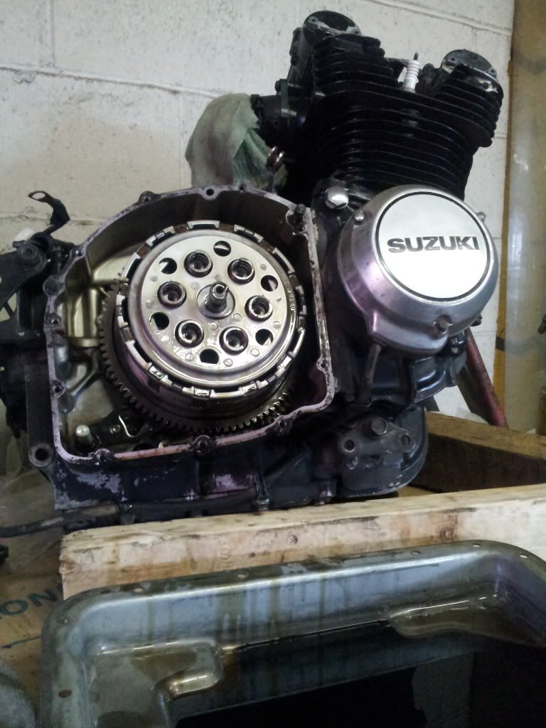
                            I finished up grinding my valve shims and swapping a few around for the best tolerances. I'm happy with the end results! This afternoon i put some bottom end gaskets on order from eBay and decided to continue my inspections of the clutch.. I pulled the side cover and checked all the friction plates and the overall clutch condition. Everything was within spec and looks relatively fresh! Heres a pic of my reassembly minus the clutch spring bolts.. I soaked the pack in some of the motor oil after i cleaned them off for reassembly


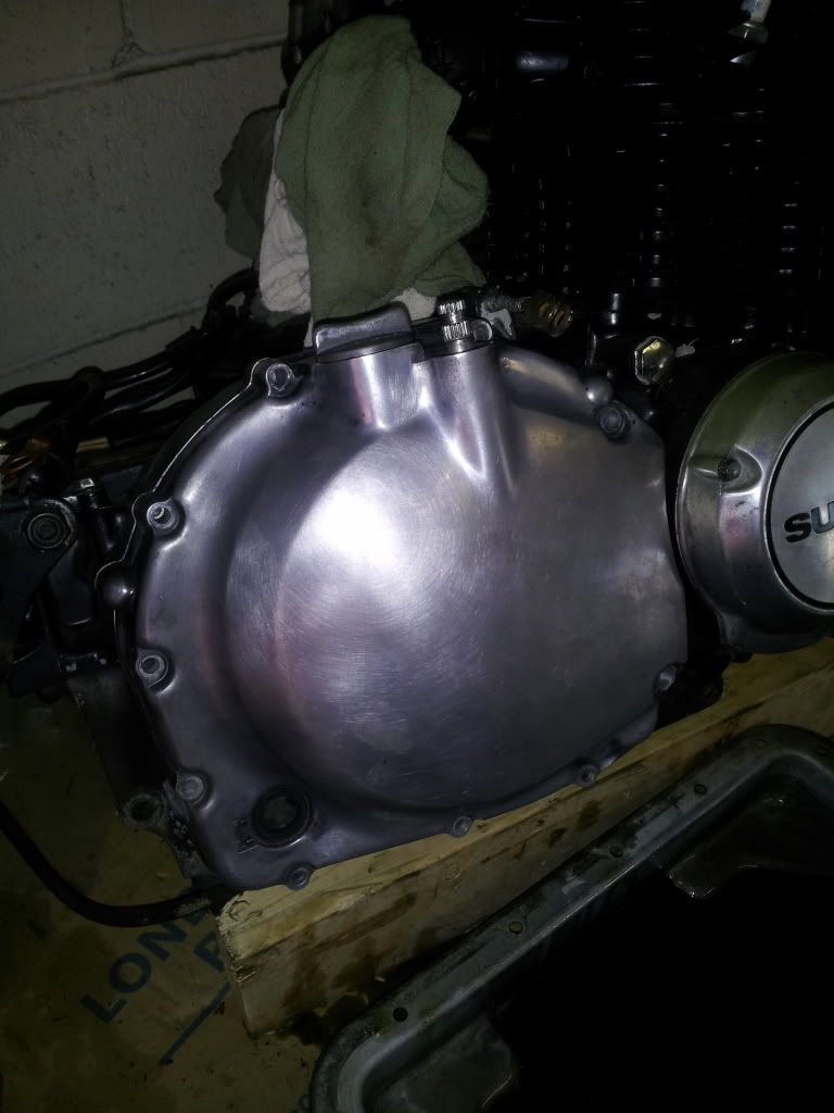
                            And here is my stripped down clutch cover. I figure i will polish it up good and clear coat eventually.. But i gotta go get some real buffing wheels for the grinder first and some compounds

                            Last edited by Guest; 07-23-2013, 10:34 PM.

                            Comment


                              #29
                              Question:

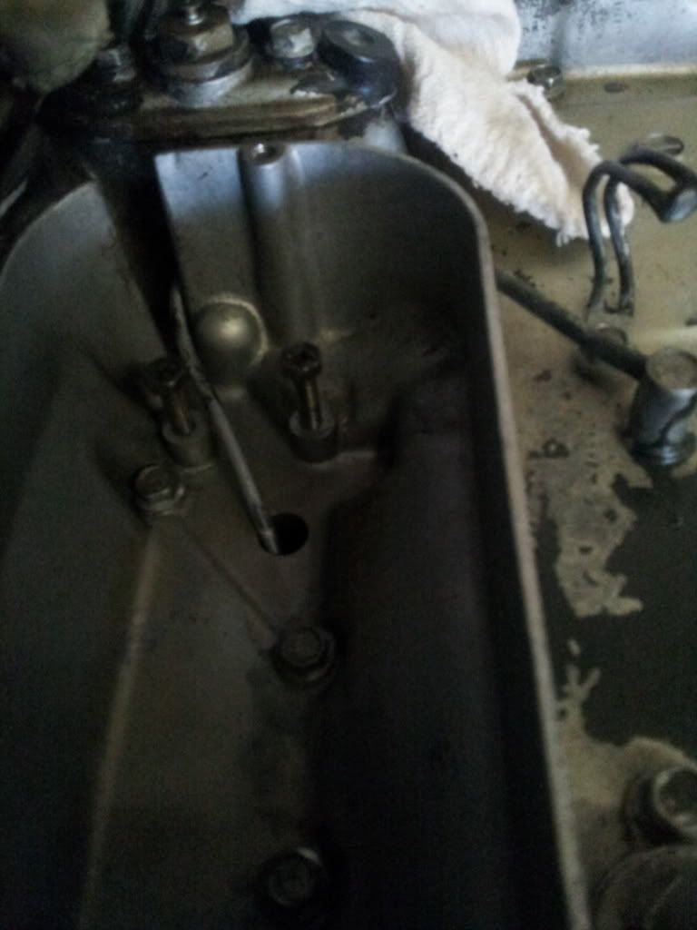
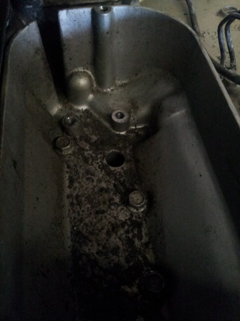
                              ****EDIT solved my own problem... Tucked back in from under the motor i found the tail end of the breather cavity. Looks to be a smaller internal seperate cavity with a hole top and bottom.. I managed to get a small light from the bottom to get a visual

                              Im on to the generator side of the motor and i decide to pull out the starter motor to clean out the pot it sits in.. Underneath the motor is a hole where i assume a breather line from the gear box runs into.. Im sure there is some debris in this hole.

                              Should i be concerned? And what cavity does this hole belong to? Can i get to it from the oil pan? Should there be any kind of plug?

                              Pics

                              Cleaned


                              dirty
                              Last edited by Guest; 07-24-2013, 03:53 PM.

                              Comment


                                #30
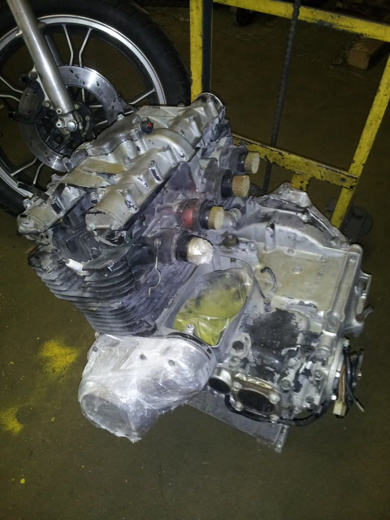
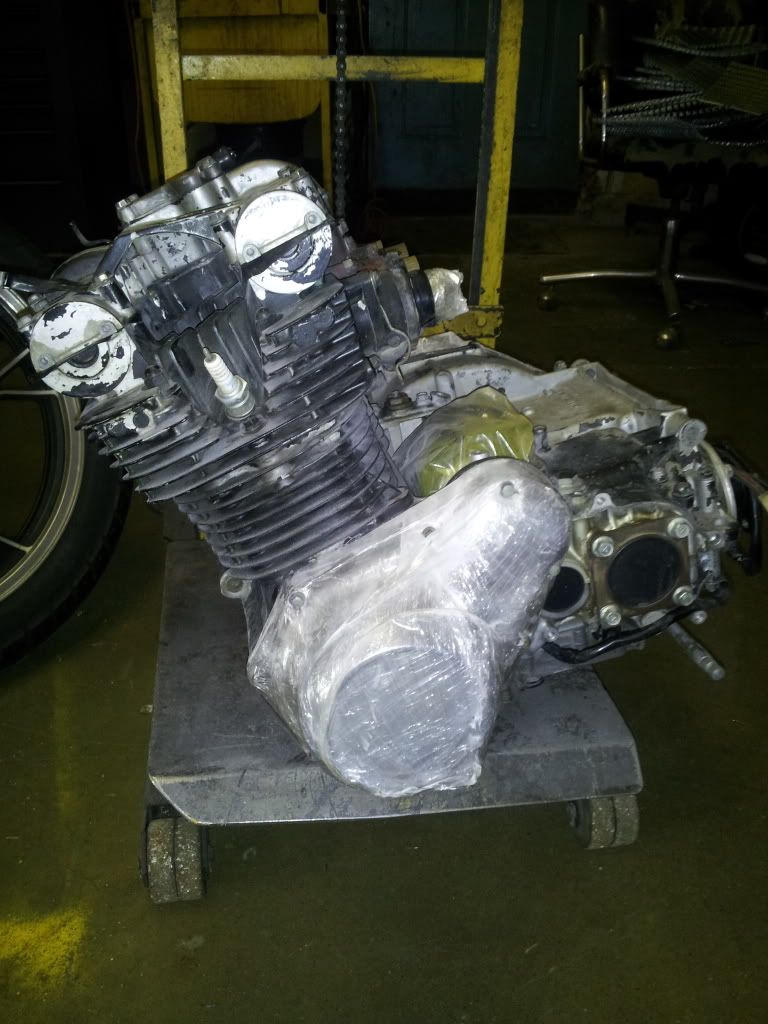
                                Headed out to media blasting later today.. Im likely to go with a very fine glass bead finish,, almost as fine as soda or flour. We dont have a local soda blasting facility here so im sol.. I even attempted my own soda blasting but results were just too tedious and time consuming... Not to mention the mess.. Ill be calling a couple other places to see if i can find a soda blast option by this afternoon

                                Ive prepared both exhaust and intakes with plugs using electrical tape to make up the tolerances to make a press fit into the bores.. Then tapped them in. Side covers are a mix of industrial skid wrap wound around each part and packing tape to add some support. I used electrical tape up top for a temporary valve cover gasket, sandwiching it between the cover.

                                Hope my creativity withstands the abuse


                                Last edited by Guest; 07-26-2013, 08:04 AM.

                                Comment

                                Working...
                                X